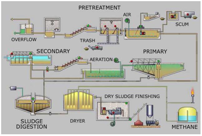
Sewage Treatment Plant Process Flow Diagram
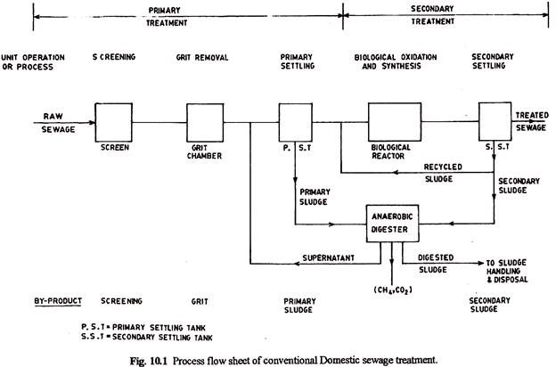
The process flow sheet of a conventional municipal sewage treatment plant comprises the unit operations of screening grit removal and primary sedimentation followed by unit process of aerobic biological treatment usually achieved by activated sludge process or trickling filter followed by secondary sedimentation. It includes major and minor flows control loops and instrumentation.
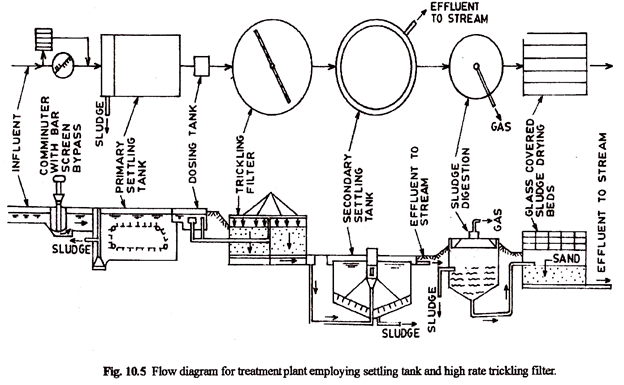
Depending on the nature of the use of the microorganisms the biological processes are categorized as suspended growth systems and attached growth systems.

Sewage treatment plant process flow diagram. With increasing infrastructural development and water usage for various purposes such as domestic and commercial there is generation of waste water. Wastewater treatment plants work 24 hours a day 365 days a year to provide an important sanitation service that protects public health and the environment. Sewers collect the wastewater from homes businesses and many industries and deliver it to plants for treatment.
In both diagrams arrows show the flow of material and symbols show tanks valves and other equipment. Secondary or biological treatment. Pid is sometimes referred to as a piping and instrumentation drawing.
Years ago when sewage was dumped into waterways a natural process of purification began. Pids are used by process technicians and instrument and electrical mechanical safety and engineering personnel. These diagrams are also called flowsheets.
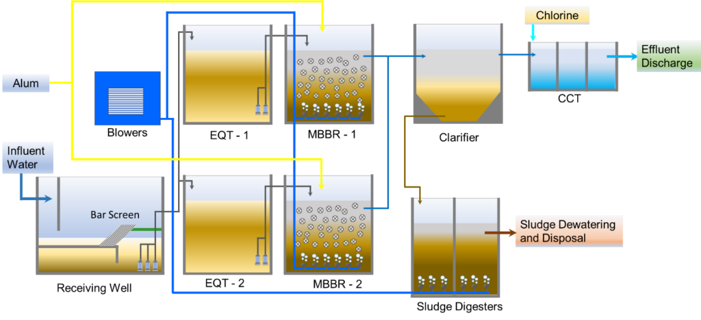
Some wastewater treatment plants have an odour control process to prevent odours affecting nearby residents. The biological treatment processes of sewage are broadly classified as aerobic anaerobic and pond processes. Sewage treatment plant process includes sewage treatment on primary secondary or biological and tertiary treatment process to improve quality of wastewater for recycle.
Most treatment plants were built to clean wastewater for discharge into streams or other receiving waters or for reuse. A process and instrument drawing pid includes more details than a pfd.
Effluent Treatment Plant Etp
 Laundry Wastewater Treatment Plant Azu Water
 Biomass Recycling Facility In Kurobe City Sewage Treatment
 A C Types Of Common Sewage Treatment Plants Flow Diagram
 Process Flow Diagram For Water Treatment Plant Schematic
 Process Flow Diagram For Water Treatment Plant Wiring


 Konya Wastewater Treatment Plant Flow Diagram 1 3


 Process Flow Diagram For Wastewater Treatment Plant Wiring
 Simplified Flowchart Of The Sewage Treatment Plant

 Sewage Treatment Plant Process Flow


 Existing Wwtp Flow Schematics And Layout City Of Reading
 Process Flow Diagram For Wastewater Treatment Plant Wiring
 Konya Wastewater Treatment Plant Flow Diagram 2 3
 Treatment Systems For Intensive Department Of Environment
.png)
 Biological And Chemical Wastewater Treatment Processes
Belum ada Komentar untuk "Sewage Treatment Plant Process Flow Diagram"
Posting Komentar