Allanson Ballast Wiring Diagram
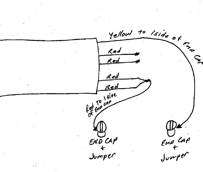
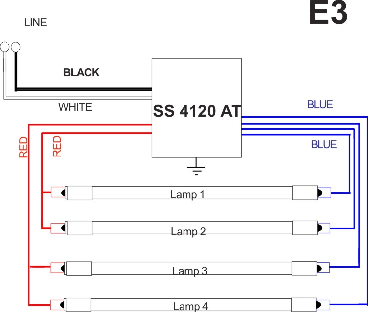
Lamps are parallel wired so if one burns out the others keep working. Instant start easy to use redblue parallel wiring which reduces wiring timeinstallation labor.
3 L Ballast Wiring Diagrams Parallel Technical Diagrams
Ease of wiring for new installations.

Allanson ballast wiring diagram. Table 1 for fluorescent sign ballasts. Visit allanson booth1526 at isa. Variety of allanson ballast wiring diagram.
At 120 v line current a. Wiring diagram catalogue number total lamp footage line current a. Eesb 832 16l ballast has an instant start easy to use redblue parallel wiring which reduces wiring timeinstallation labor and rewiring of the lamp sockets is required when used as a replacement for ferromagnetic ballasts.
It shows the components of the circuit as simplified forms as well as the power and also signal connections between the tools. 29 degrees c high output 800ma rs lamps 120277347 volts 60 hertz. Rewiring of the lamp sockets required when used as a replacement for ferromagnetic ballasts rewiring diagrams provided 5 models replace 26 magnetic ballasts for less inventory and increased savings.
Eesb series electronic sign ballasts wiring diagrams lead lengths and case dimensions 1 800559 3659 lead lengths and case dimensions. A wiring diagram is a streamlined standard photographic representation of an electric circuit. Double check the actual wiring with the wiring diagram on the label and look for.
Wiring or the wiring is incorrect. Depending on the ballast model. Changing the wiring on a fluorescent light fixture from series to parallel involves changing the ballast from a series to a compatible parallel ballast.
At 347 v input watts open. Guaranteed by fri aug. Series ballasts can only be wired in series according to the diagram on the ballast.
Parallel ballasts can only be wired in parallel according to the diagram on the ballast. Wiring diagrams for allanson lighting components eesb electronic ballasts are simpler with half the connections found in old style magnetics. Wiring diagram aspl xxcw dsmv this document is complimentary to the speedlamp instruction manual 21 322 and must be referenced after reading the manual.
At 277 v line current a. The allanson lighting component inc. On allansons 696 and 4120 the readings should be taken between the blue.
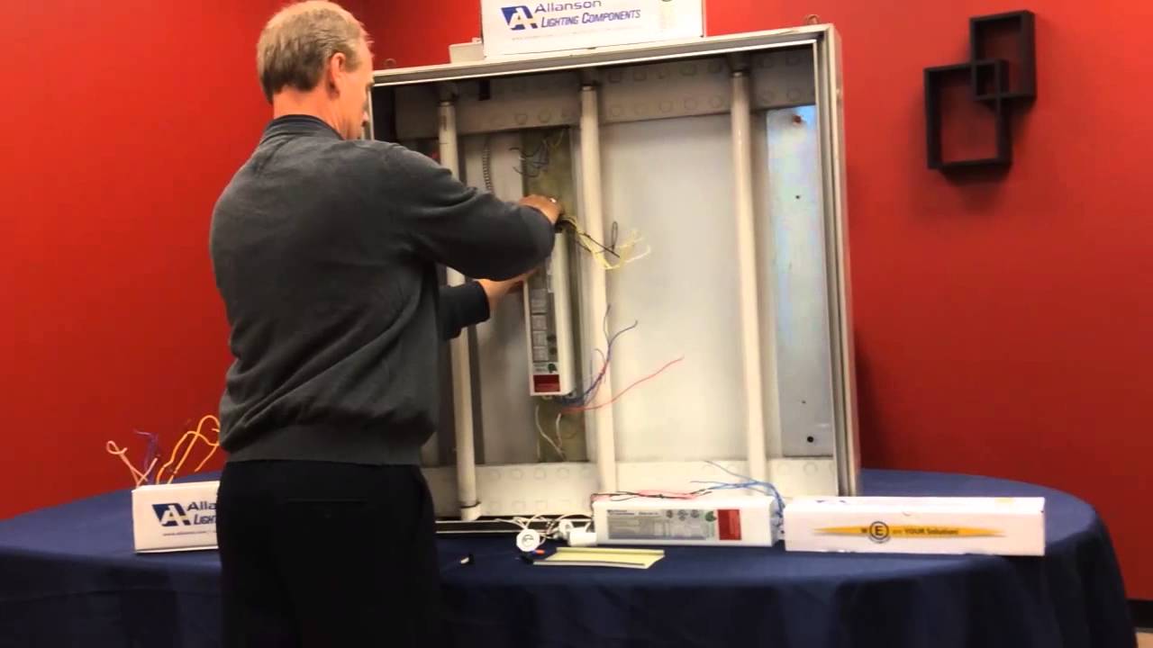
There should be no power ever to the lampholders for any reason during installation. Allanson ballast electronic for sign rss 696 at simple easy wiring. Allanson magnetic ballast trouble shooting procedures primary current.
High output fluorescent sign ballasts. Allanson electric sign ballast repair part 296 bft 120v 2 lamps 12 16 flashable see more like this.
 Rss Fluorescent Ballasts Allanson Corporate

Untitled


 Ballast Icn 4p32 N Wiring Diagram Wiring Diagram
 Help With T5 80w Bulbs And Workhorse 5 Ballasts Reef2reef
Specifications Guide Eesb Rss Customer View 8
 Electronic Sign Ballast Wiring Diagram Schematics Online
 Allanson Electric Sign Ballast Repair Part 272 At 277v 1 Or 2 Lamps 4 12 Nos
 Sign Ballasts Smart Wire Parallel Wire Keystone
Allanson Lighting Components Specifications Guide Eesb Rss
Untitled
 Electronic Sign Ballast Allanson Corporate

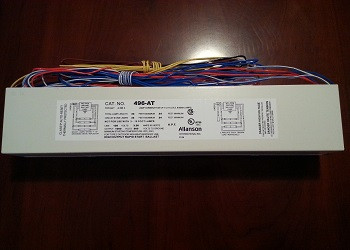 Allanson 496 At 120v High Output Fluorescent Sign Ballast


Allanson 432 Ballast Wiring Diagram Wiring Diagram
 Allanson Fluorescent Ballast Wiring Diagram
Spot Welding Electrical Diagram Wiring Diagram
 696 At Allanson Magnetic Sign Ballast
Belum ada Komentar untuk "Allanson Ballast Wiring Diagram"
Posting Komentar