Ethane Cracker Process Flow Diagram
Ethane must be cracked to make ethylene 26. Between a variety of processes the thermal crack ing of hydrocarbons in the presence of steam steam cracker is mostly used.
The process can include a premixed h 2 addition in the feed.
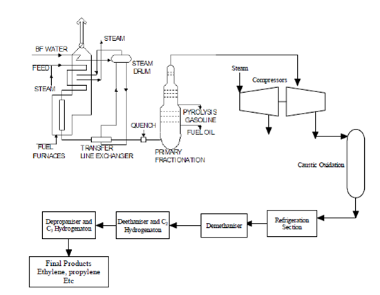
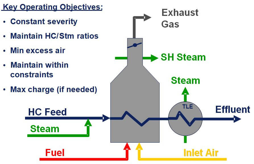
Ethane cracker process flow diagram. In modern crackers where the furnace process is highly optimized a more accurate control is required. Dilution steam can also be used for decoking the furnace making good rangeability a. The cracking process involves breaking up the carbon and hydrogen molecules and rearranging them.
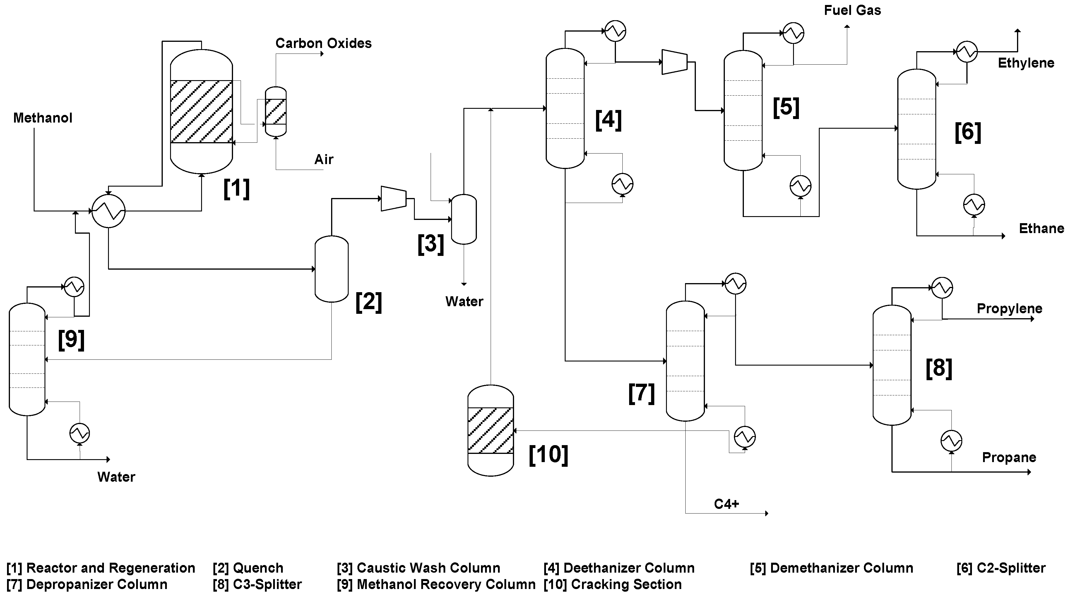
Acid gas removal dehydration fractionation train hydrogenation reactor an ethylene splitter and steam cracking refer to appendix b for the process flow diagram. Control systems the criticality of the steam flow control system can vary. Initially an ethane propane mixture is fed to furnaces in which under high severity conditions it is cracked forming ethylene propylene and other byproducts.
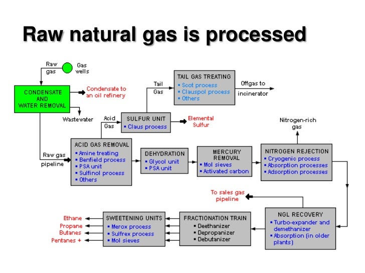
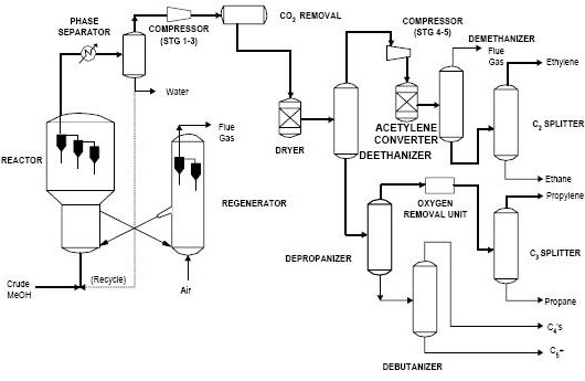
Regardless of the process type all plants require process analytical equipment to collect reliable and accurate process data for process con trol product quality and plant safety. The new process alternative to convert ethane to ethylene is a short contact time reactor a few milliseconds in which the reaction takes place in the presence of a foam monolith of alumina supported pt sn catalyst. Carbon dioxide must first be removed from the inlet shale gas in the acid gas removal section.
The ethane crackers fuel consists of a mixture of recycled tail gas hydrogen rich and natural gas methane with a heating value of 523 btuscf. This process diagram shows an ethylene production process via the cracking of an ethane propane mixture cracking and quenching. Linde 713 873 1708.
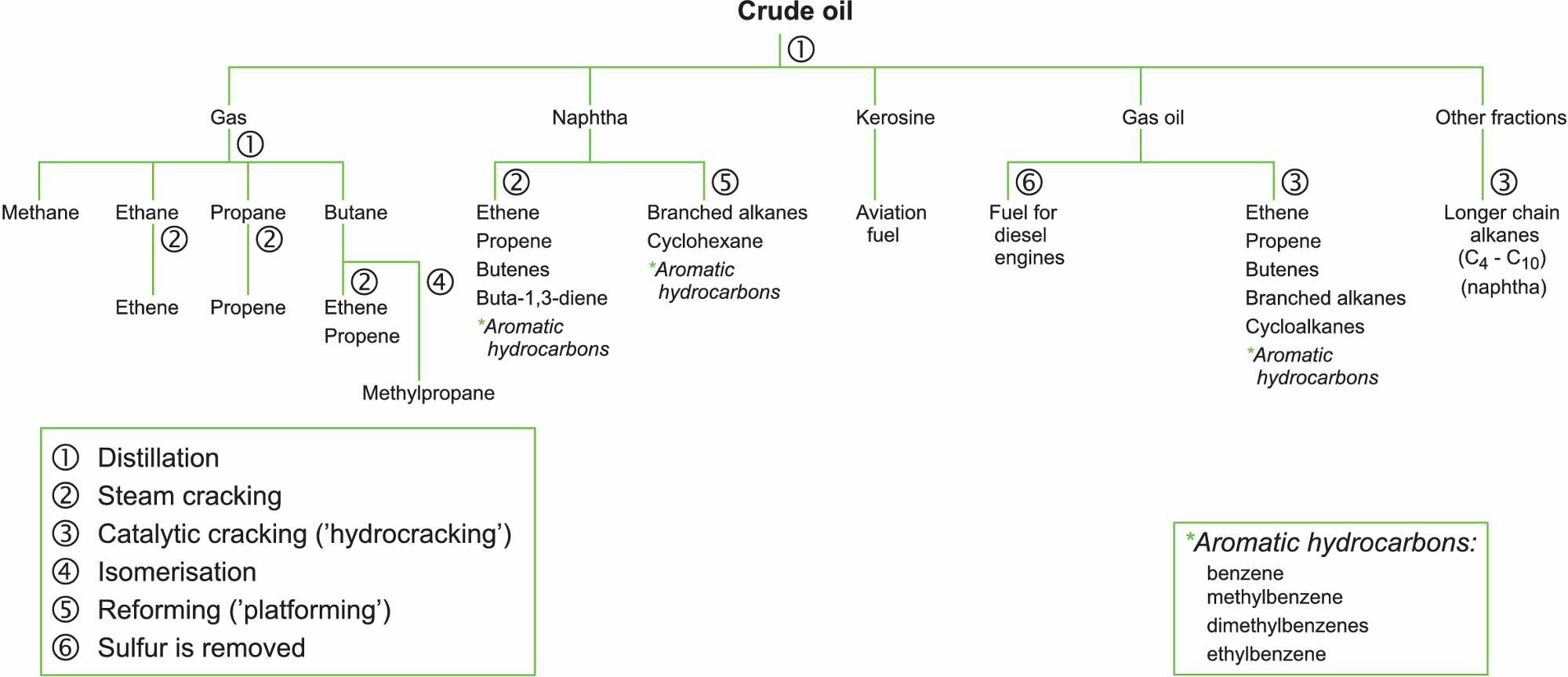
Liquids ethane and lpg and heavy liquids ie naphtha and gas oils. Advances in ethane cracking. Full range naphtha frn is thought of as any hydrocarbon that boils in the.
Poor performance of the steam supply valve can lead to excessive fouling of the cracker. Cracking is accomplished by heating ethane to greater than 800c 1500f in the cracker furnace. The process description and process flow diagrams given in the report are based on an ethanepropane feedstock.
Normal operation assumes five furnaces continuous operation and one furnace on hot stand by or decoking operations. Steam cracker 170 mw heat duty modeled as 2 100mw separate pyrolysis furnaces each furnace 100 mw capacity operates at 80 capacity. Natural gas liquids ngls are composed essentially of ethane propane and butanes.
The proposed design consists of six main sections.
Mathematical Model For Ethane Pyrolysis In An Industrial
 Flare Minimization Practices Improve Olefins Plant Start Ups
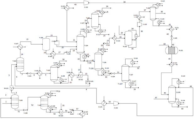
 Simulation And Optimization Of The Ethane Cracking Process
 Shale Gas To Ethylene G2 Processdesign
 Efficiently Cracking Hydrocarbons In Ethylene Furnaces
 Cracking The Ethane Cracker
 Non Catalytic Ethane Cracking Using Concentrated Solar
 Typical Flow Diagram For A Naphtha Steam Cracker Figure Was
Ethylene Production From Tennessee Fracked Natural Gas
Process Economics And Safety Considerations For The

 Techno Economic Performance Of The Coal To Olefins Process
 Petrochemical Wikipedia
 Energy Flow In A Typical Naphtha Steam Cracker With The Fuel
 Schematic Of Ethane Steam Cracking Furnace Download
 Integrated Fcdh Reactor System With Ethane Cracker
 Olefins Markets Innovations Ptt Global Chemical Public
Skogskemi Olefins Value Chain
 Processes Free Full Text A Techno Economic Comparison
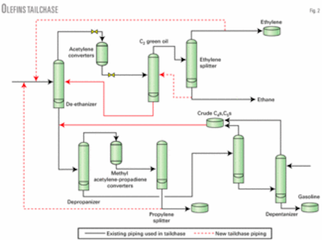
 Cracking The Ethane Cracker
 12 3 Types Of Coal Derived Chemicals Netl Doe Gov
 Cracking The Ethane Cracker

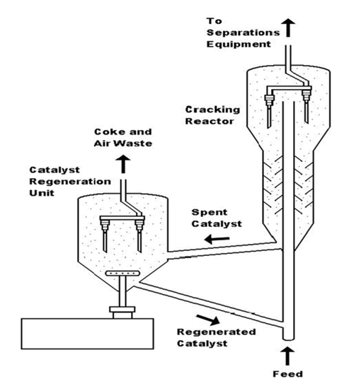
 Fluid Catalytic Cracking Process Download Scientific Diagram

 Shale Gas To Ethylene G1 Processdesign
Belum ada Komentar untuk "Ethane Cracker Process Flow Diagram"
Posting Komentar