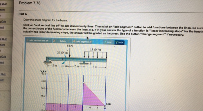
Problem 778 Part A Draw The Shear Diagram For The Beam
25 9 m 20 knm. Solved problem 7 48 part a draw the shear diagram for.
 Mastering Engineering Assignment 12 Beams Engineering
Mastering engineering assignment 12 beams engineering mechanics statics.
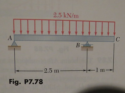
Problem 778 part a draw the shear diagram for the beam. And bending moment diagram how to use shear force exles of a graphically for body diagram draw the shear and moment diagram for beam cd 20 points of the position. Click on add vertical line off to add discontinuity lines. This tutorial goes over how to draw the shear force diagram bending moment diagram and deflected shape of a simply supported beam with a distributed load and a point load.
View homework help mastering engineering assignment 12 beams engineering mechanics statics from 440 221 at rutgers university. Follow the sign convention. Solved draw the shear and moment diagram for beam cd drasolved part a draw the shear diagram for beam follsolution to problem 438 relationship between load sheardraw the shear force.
This problem has been solved. 778 draw the shear and moment diagram for the beam. 9 m 20 knm.
Shear force and. Follow the sign convention. Then click on add segment button to add functions between the lines.
Follow the sign convention. Expert answer 90 71 ratings previous question next question get more help from chegg. 1 answer to problem 759 part a draw the shear diagram for the beam.
Be sure to indicate the correct types of the functions between the lines eg. Problem 778 part a draw the shear diagram for the beam. Correct problem 778 part a draw the shear diagram for the beam.
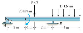
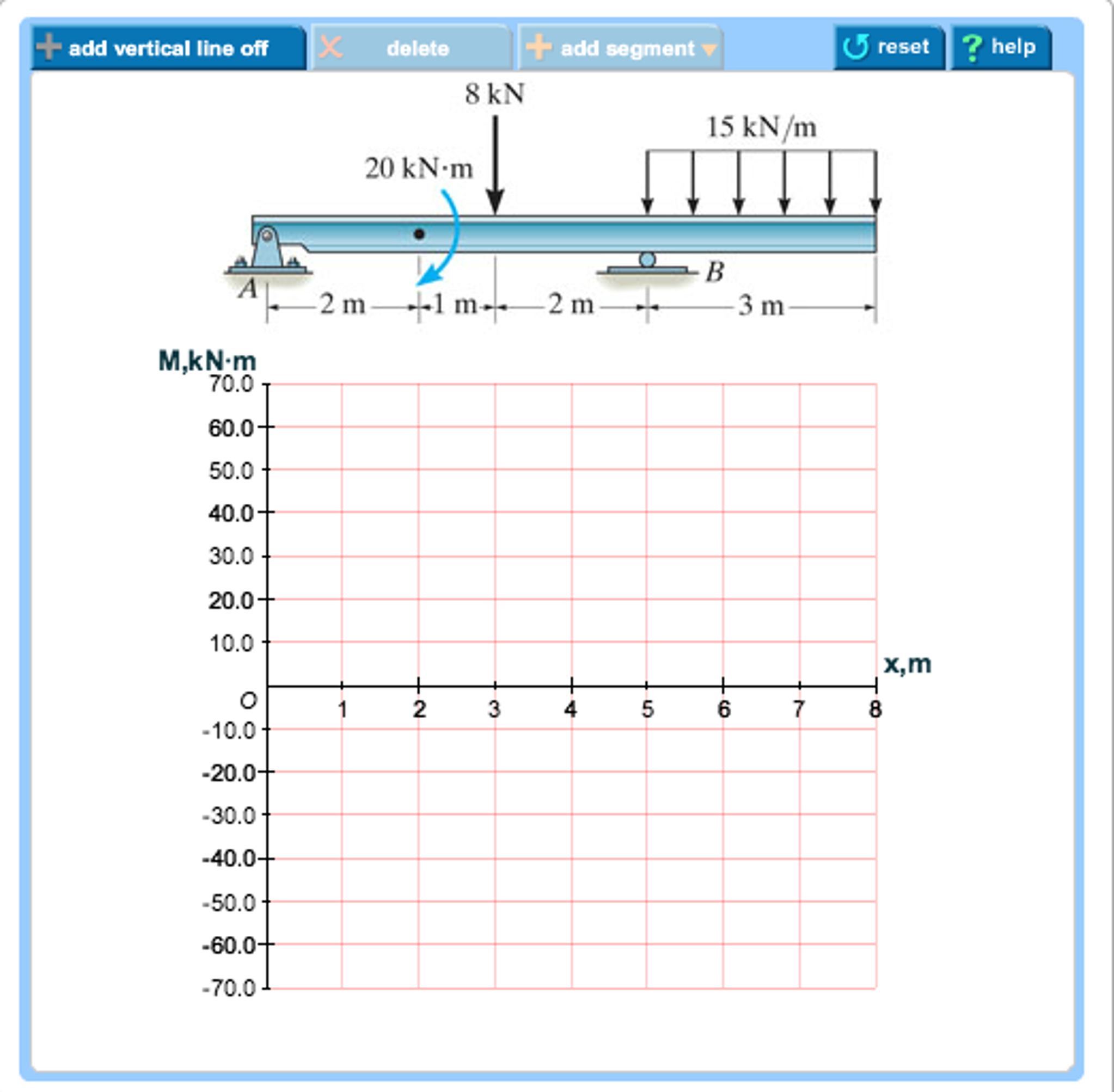
Forces in beams beams various. Figure 1 part b draw the moment diagram for the beam. Draw the shear and moment diagrams for the beam shown in the figure.
778 draw the shear and moment diagram for the beam. Problem 785 part a draw the shear diagram for the beam. Assume the supports at a and c are rollers and b and d are pin connections.
How to draw shear force and bending moment diagrams. Note 1 you should not draw an extra discontinuity line at the point where. 329 6 1 draw the shear and moment diagrams for shaft solved part a draw the shear diagram for beam foll solution to problem 434 relationship between load shear 329 6 1 draw the shear and moment diagrams for shaft solution to problem.
Figure 1 click on add vertical line off to add discontinuity lines. Draw the shear and moment diagrams for the compound beam shown in the figure. Then click on add segment button to add functions between the lines.
 Us20160187547a1 Color Material Color Material Dispersion
Geotechnical Baseline Report Gblr I 85 Bridge Over Rocky
 Shear Strength Criteria For Design Of Rc Beam Column Joints
 Hibbeler Statics Solution Chapter 7 1
 Shear Strength Criteria For Design Of Rc Beam Column Joints
 Mastering Engineering Assignment 12 Beams Engineering
 Us20160067239a9 Pharmaceutical Compositions And
 Pdf Vector Mechanics For Engineers Chapter 07 Pdf Ziad
Problem 5 1
 Assessment Of The Ore Forming Process Of The Gejiu Tin
 Shear Force And Bending Moment Diagrams Example 3 Distributed Load
 Solved A Draw The Shear Diagram For The Beam Follow The
 Solved Problem 7 78 Part A Draw The Shear Diagram For The
Solution Manual Engineering Mechanics Statics 12th Edition
International Journal Of Soft Computing And Engineering
 Solved Statics Vector Mechanics For Engineers 10th Editio
 Drawing Shear And Moment Diagrams Example Mechanics Of
329 6 1 Draw The Shear And Moment Diagrams For The Shaft
 Mastering Engineering Assignment 12 Beams Engineering
329 6 1 Draw The Shear And Moment Diagrams For The Shaft
 Shear Transfer Across A Crack In Reinforced High Strength
 Hibbeler Statics Solution Chapter 7 1
Statics And Dynamics Me35a Fall 2008
Belum ada Komentar untuk "Problem 778 Part A Draw The Shear Diagram For The Beam"
Posting Komentar