Control Circuit Diagram
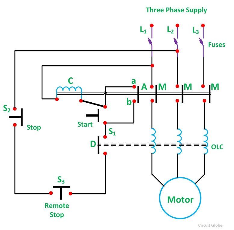
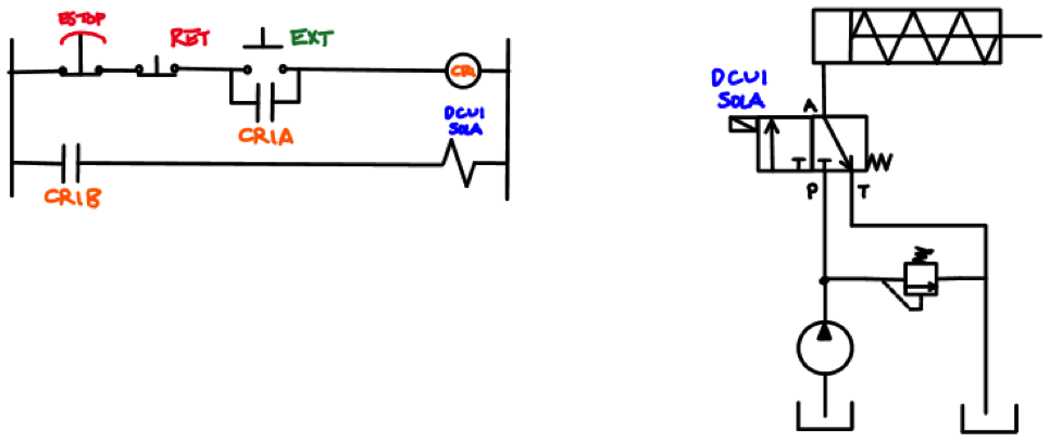
The presentation of the interconnections between circuit components in. To stop either circuit forward or backward we require some means for the operator to interrupt power to the motor contactors.
 Water Level Control Circuit Remotecontrolcircuit Circuit
A circuit diagram electrical diagram elementary diagram electronic schematic is a graphical representation of an electrical circuita pictorial circuit diagram uses simple images of components while a schematic diagram shows the components and interconnections of the circuit using standardized symbolic representations.

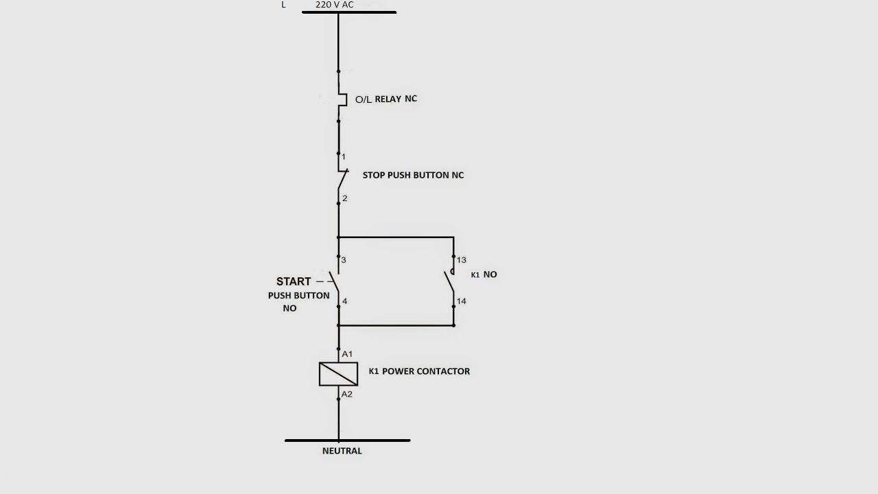
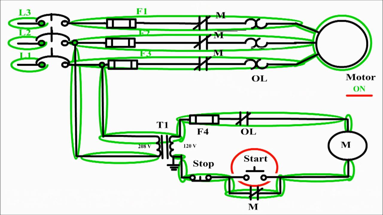
Control circuit diagram. This book contains examples of control circuits motor starting switches and wiring diagrams for ac manual starters drum switches starters contactors relays limit switches and lighting contactors. Imagine trying to wire a pushbutton station for a 100a motor using 3 awg conductors. Figure 2 shows a typical line or schematic diagram.
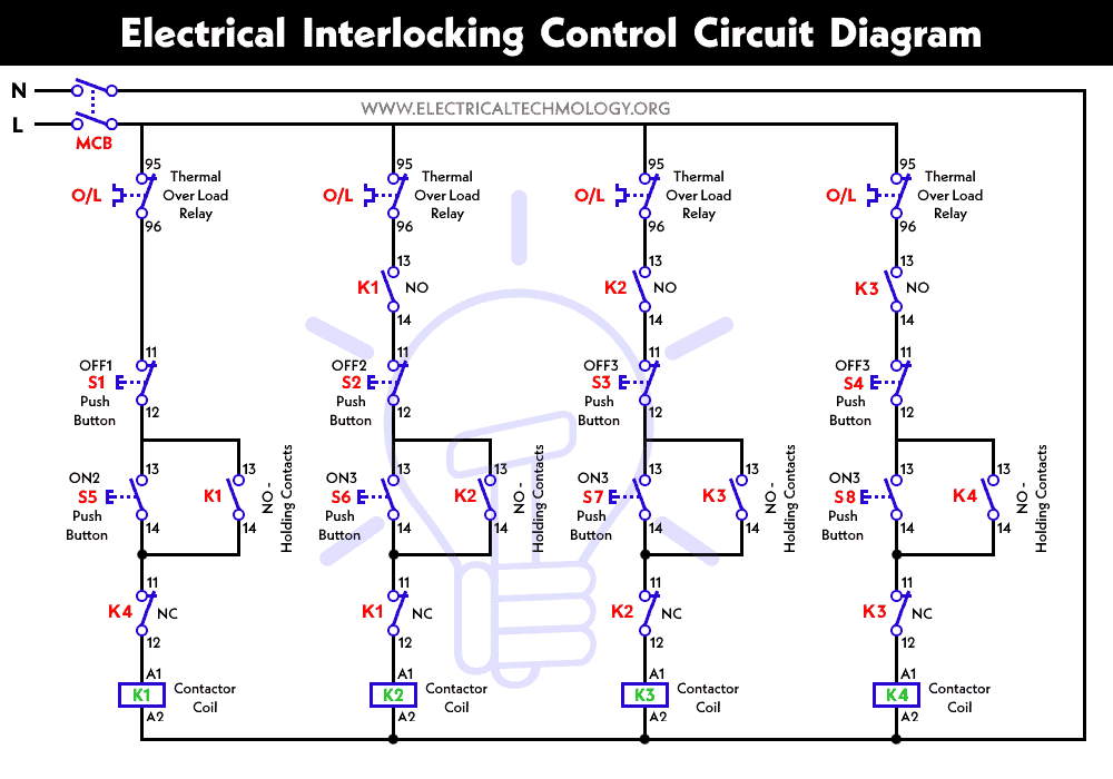
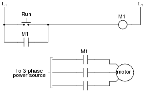
As the circuit exists right now the motor will run either forward or backward once the corresponding pushbutton switch is pressed and will continue to run as long as there is power. A special type of overcurrent protection device used commonly in motor control circuits is the overload heater. Line diagrams also called schematic or elementary diagrams show the circuits which form the basic operation of the controller.
Two wire control circuits and three wire control circuits. These devices are connected in series with the motor conductors and heat up slightly under normal current conditions. They are an ideal means for troubleshooting a circuit.
A two wire control circuit can be a simple switch that makes or breaks connection to a motor figure 18 1. Ladder diagram basics 3c 3 wire control duration. They do not indicate the physical relationships of the various components in the controller.
Many smaller motors use the same size. Mechanical connection between two components such as those shown in electrical symbols 5 8. Control circuits can be divided into two major types.
Pete vree 27952 views. Field wired or installed components. Control circuitsschematic diagrams wiring diagrams and reading schematic diagrams 1.
Line diagrams show circuits of the operation of the controller. The star delta y δ 3 phase motor starting method by automatic star delta starter with timer. Factory wired or.
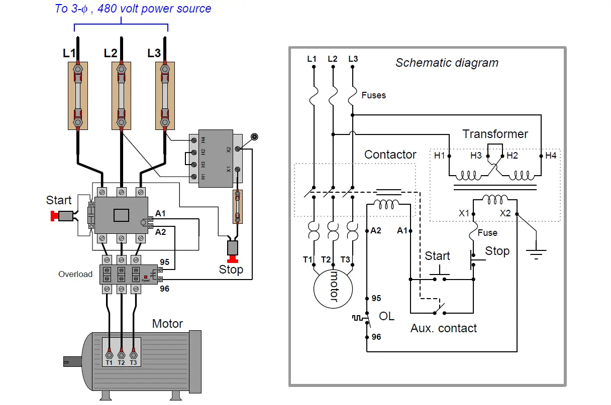
Three phase motor connection stardelta y δ reverse forward with timer power control diagram. Three phase motor connection schematic power and control wiring installation diagrams. Motor control circuits motor control circuits are an effective way to reduce cost by using smaller wire and reduced amperage devices to control a motor.
Components used only in special circumstances. Although the heater elements are connected in series with the motor lines as fuses would be.
 D O L Circuit Diagram Group Electrical Schemes
 Motor Control Circuits Automations Schematics Wiring
 Motor Control Circuit Wiring Instrumentation Tools
 3 Wire Control Schematic N5 Electrical Schemes
 3 Phase Contactor Circuit Diagram Wiring Start Stop Pdf
 Motor Control Circuit Diagram Pdf Bookmark About Wiring
 Control Circuit Diagram Catalogue Of Schemas
 Ac Motor Control Circuits Ac Electric Circuits Worksheets
 Control Circuit Diagram In Addition Star Delta Control
 Motor Starter Circuit Diagram Pdf Car Wiring Diagram And
 Ac Motor Control Circuits Ac Electric Circuits Worksheets
 Motor Starter Circuit Wiring Diagram Wiring Diagram
Ac Motor Control Circuits Ac Electric Circuits Worksheets
 Motor Control Circuit Diagram Start Stop 3 Wire Control
 Infrared Purpose Of 1 Microfarad Capacitor In Ir Receiver

 Star Delta Starter Motor Control With Circuit Diagram In
 Motor Starter Circuit Diagram Pdf Car Wiring Diagram And
 Motor Circuit Diagram Pdf Machine Learning
 Control Circuit Diagram Catalogue Of Schemas
 3 Wire Control Schematic N5 Electrical Schemes
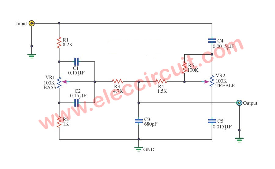 Passivetonecontrolcircuit Controlcircuit Circuit Diagram
 Remote Controlled Alarm Circuit
Belum ada Komentar untuk "Control Circuit Diagram"
Posting Komentar