Pressure Transducer Wiring Diagram
It shows the components of the circuit as streamlined shapes as well as the power as well as signal connections in between the devices. The 4 20ma signal flows through two separate cable cores between the transmitter and control panel.
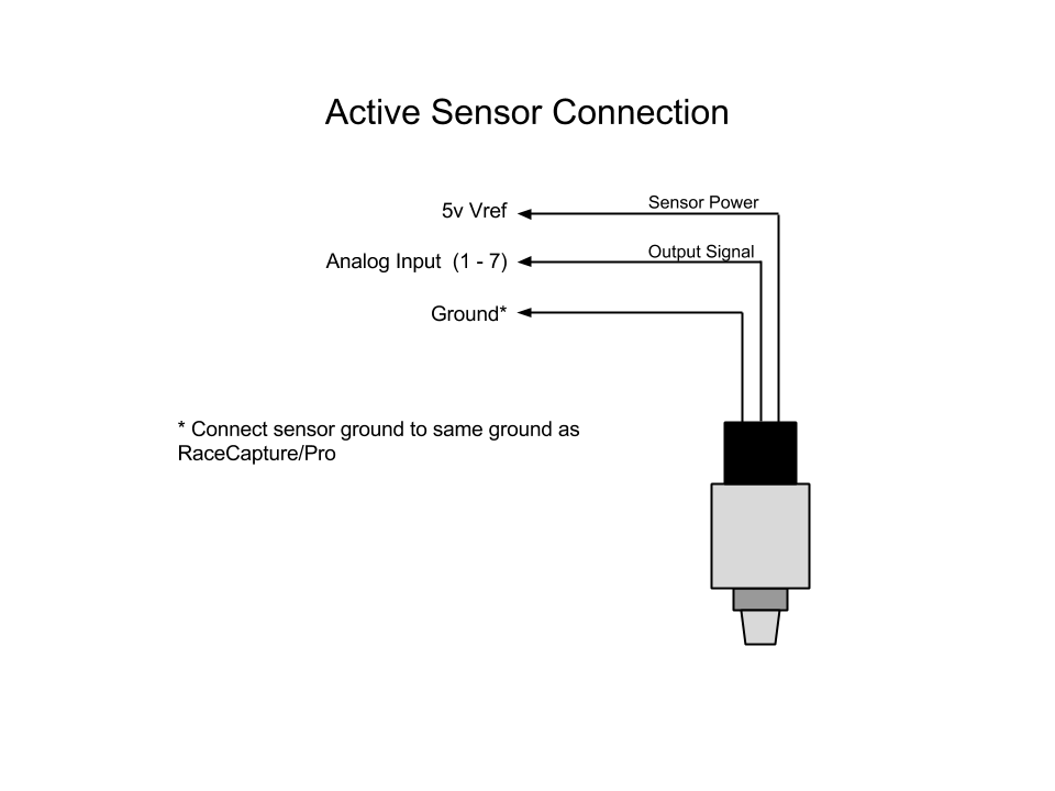
![]() 3 Wire
3 Wire
Then disconnect the wire that runs form the transmitters signal to the control circuit.
Pressure transducer wiring diagram. So i have excitation for both sensors hooked up to 47 63 and my signal hooked up to 1 and 4. 3100 series and 3200 heavy duty series compact oem pressure transmitters exceptional long term stability 0 100 psi to 0 30000 psi ranges 0 7 bar to 0 2200 bar high proof pressures with all stainless steel wetted parts broad choice of outputs electrical connectors and pressure ports. A wiring diagram is a streamlined conventional pictorial representation of an electric circuit.
Help wiring a pressure transducer. A wiring diagram is a streamlined standard photographic depiction of an electric circuit. It so happens that on some vehicles cadillacs the high pressure sensor is connected to the other sensor voltage reference line.
So i scrapped the power supply i was using and wired up my pressure transducer to the daq using the 5 volt terminal as defined by the chart below from user manual daqpad 6015. So a shorted sensor will render the crank sensor inoperable. Now place the voltmeter lead onto the transducers signal and the voltmeter onto common.
Fully isolated 4 wire the transmitter and control panel use separate power supplies. With no pressure applied the transmitter should provide a voltage output as specified on the units data sheet say 01 vdc. Assortment of 3 wire pressure transducer wiring diagram.
It shows the components of the circuit as simplified shapes and the power as well as signal connections between the devices. Collection of ashcroft pressure transducer wiring diagram. Model tje pressure transducers are all welded stainless steel sensors built for rugged industrial applications that require high accuracy and measurement stability.
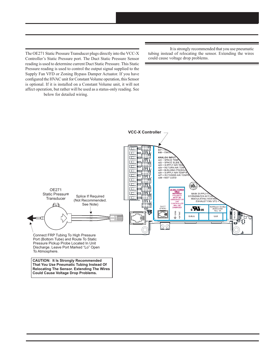
It is assumed that the power to drive the 4 20ma loop is derived from the control panel.
![]() Differential Pressure Transducer Output 4 20ma Hart
Differential Pressure Transducer Output 4 20ma Hart
![]() Pressure Transducers Installation And Use Omega Engineering
Pressure Transducers Installation And Use Omega Engineering
 Pressure Transducer All About Circuits
Wiring Diagram For Pressure Transducer Wiring Diagrams Folder
Transducer Wire Diagram Wiring Library
Pressure Transducer Circuit Diagram New 3 Wire Pressure
 Pressure Sensor Wiring Diagram
Pressure Transducer Wiring Diagram Albertasafety Org

 3 Wire Pressure Sensor Circuit Diagram Wiring Diagram
![]() 4 Wire Pressure Transducer Wiring Diagram Wiring Diagram T1
4 Wire Pressure Transducer Wiring Diagram Wiring Diagram T1
![]() Pressure Transducers Installation And Use Omega Engineering
Pressure Transducers Installation And Use Omega Engineering
 Apb5 Pressure Transmitter 0 5v Thermosense Direct
 Use Of Submersible Pressure Transducers In Water Resources

 4 Wire Pressure Transducer Wiring Diagram Wiring Library

![]() Pressure Transducer Wiring Repairs Restorations Mods
Pressure Transducer Wiring Repairs Restorations Mods
![]() 4 20ma Pressure Transducer Wiring Diagram Gallery Wiring
4 20ma Pressure Transducer Wiring Diagram Gallery Wiring
![]() Begginers Guide To Wiring Diagrams Wiring Library
Begginers Guide To Wiring Diagrams Wiring Library
![]() 3 Wire Pressure Transducer Wiring Diagram Sample
3 Wire Pressure Transducer Wiring Diagram Sample
![]() Simple Guidance For You In Ashcroft Diagram Information
Simple Guidance For You In Ashcroft Diagram Information
![]() Pressure Transducer Wiring Wiring Diagram Perfomance
Pressure Transducer Wiring Wiring Diagram Perfomance
 Wiring Diagram For Pressure Transducer Wiring Diagram
![]() Ashcroft Pressure Transducer Wiring Diagram Gallery Wiring
Ashcroft Pressure Transducer Wiring Diagram Gallery Wiring
![]() Wiring Diagram For Pressure Transducer Wiring Diagram
Wiring Diagram For Pressure Transducer Wiring Diagram
Pressure Transducer Overview Installation Pressure Transducer
Belum ada Komentar untuk "Pressure Transducer Wiring Diagram"
Posting Komentar