Cross Hydraulic Valve Diagram
Cross b c series handle 1v1703. Automatic sequence valve planter markers.

Contact cross if the valve allows the hydraulic equipment to creep excessively.
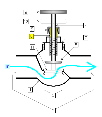
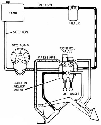
Cross hydraulic valve diagram. Cross manufacturing is a leading manufacturer of a complete line of hydraulic components. Use an open center valve for open center applications and a closed center valve for closed applications. The diagram shows a winch powered by a hydraulic motor.
Control valve repair parts. High pressure ball valves. Valves are available with float and detent and also open or closed center.
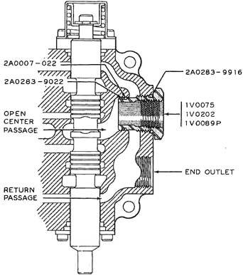
The valve until the chamfer on the spool is flush with the bottom of the seal gland. The hydraulic pump and motor must be matched to the torque requirements of the winch. Directional valves route the flow of fluid into ports a and b based on the application.
Install o ring spool seal into. Hydraulic control valves cross. 43 hydraulic valve operation.
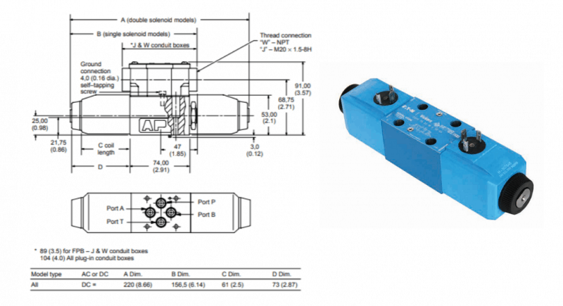
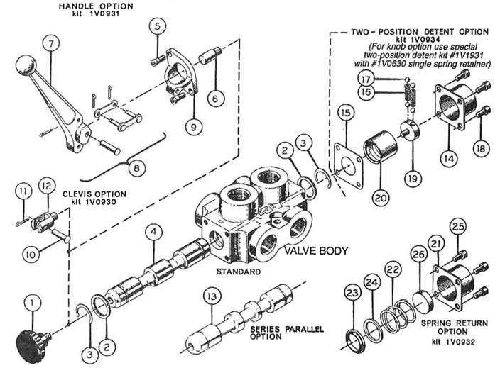
Cross manufacturing hydraulic directional control valves. Spool seals are easily replaced by removing the handle bracket end cap and o rings. Cross b series.
Cross spool type directional control valves are not field repairable except for seal replacement and relief valve cartridges. Hydraulic control valves cross. Cross b series control valves are available with 1 to 3 spools up to 3000 psi working pressure and 30 gpm flow rate.
If in doubt check with your tractor dealer. Welded and tie rod cylinders directional flow and pressure control valves hydraulic gear pumps and motors filters accumulators gear boxes cross piston adapters and manifolds. The new versions have larger cross section the old was 070 the new is 103 and different.
Hydraulics systems diagrams and formulas. The directional control valve with built in relief features optional flow control to control the speed of the winch. Gresen hydraulics r model v20 sectional body directional control valve.
Cross b series hydraulic control valves. Cross manufacturing sbaf2j 143430 sba series cast iron double spool monoblock hydraulic directional control valve with joystick 1st spool 4 position float 2nd spool 3 position open centered 34 x 34 x 12 npt female 2500 psi grey. Directional control valves technicalservice manual valve selection and application.
Converta cd cs or ca valves should never be used for metered heavy load lifting loaders or similar applications. Explaining directional valve repair full dismantle and reassembly.
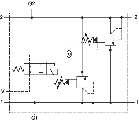
 Crossover Relief Valves Related Fluid Power
 Valve Wikipedia
 Hydraulic Manifold Schematic Wiring Diagrams Folder

 The Basics Of Hydraulic Spool Valves Cross Company
 Hydraulics Systems Diagrams And Formulas Cross Mfg
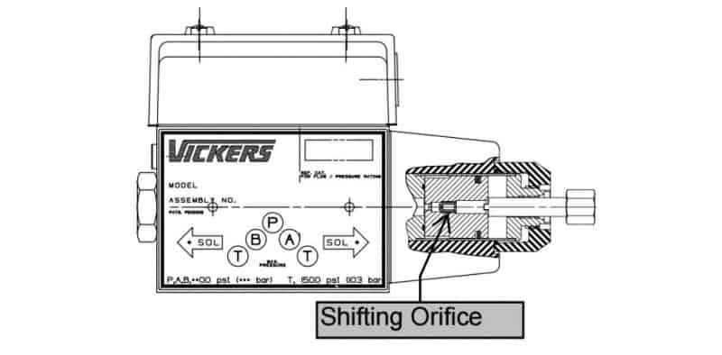 Stop Hydraulic Shock With Soft Shift Hydraulic Control
 Book 2 Chapter 12 Fluid Motor Circuits Hydraulics
 Valves
Untitled
 A The Hydraulic Circuit Of The Semiactive Damper B A
 Hydraulic Jack Hydraulic Car Jack Diagram A Single


 Submarine Hydraulic Systems Chapter 4
 Needle Valve Types Function Applications Tameson
 1 Stock No Model Code Q7

 Hydraulic Steering 101 For Off Road Vehicles Cross Company
 Rvc0 S10 Valve Series Vis Hydraulics
Help With Loader Valve Ih 2400 And Cross Sba22
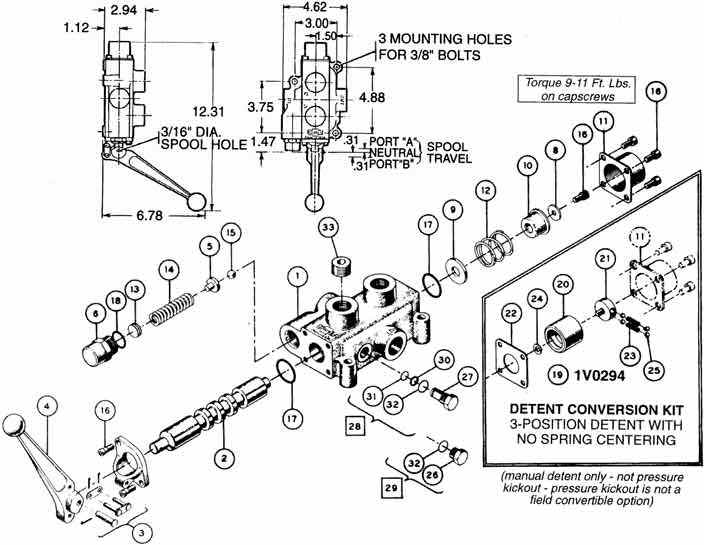
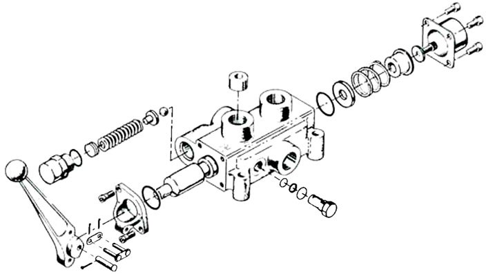 Directional Control Valves Service Manual Cross Mfg
 Model Cv Valve Parts Cross Mfg
 Sd Double Selector Parts Cross Mfg
Help With Loader Valve Ih 2400 And Cross Sba22
 Cross Over Relief Valve 411615
Power Beyond Option Parts Cross Mfg
Belum ada Komentar untuk "Cross Hydraulic Valve Diagram"
Posting Komentar