Brayton Cycle Ts Diagram
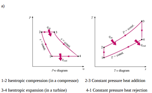
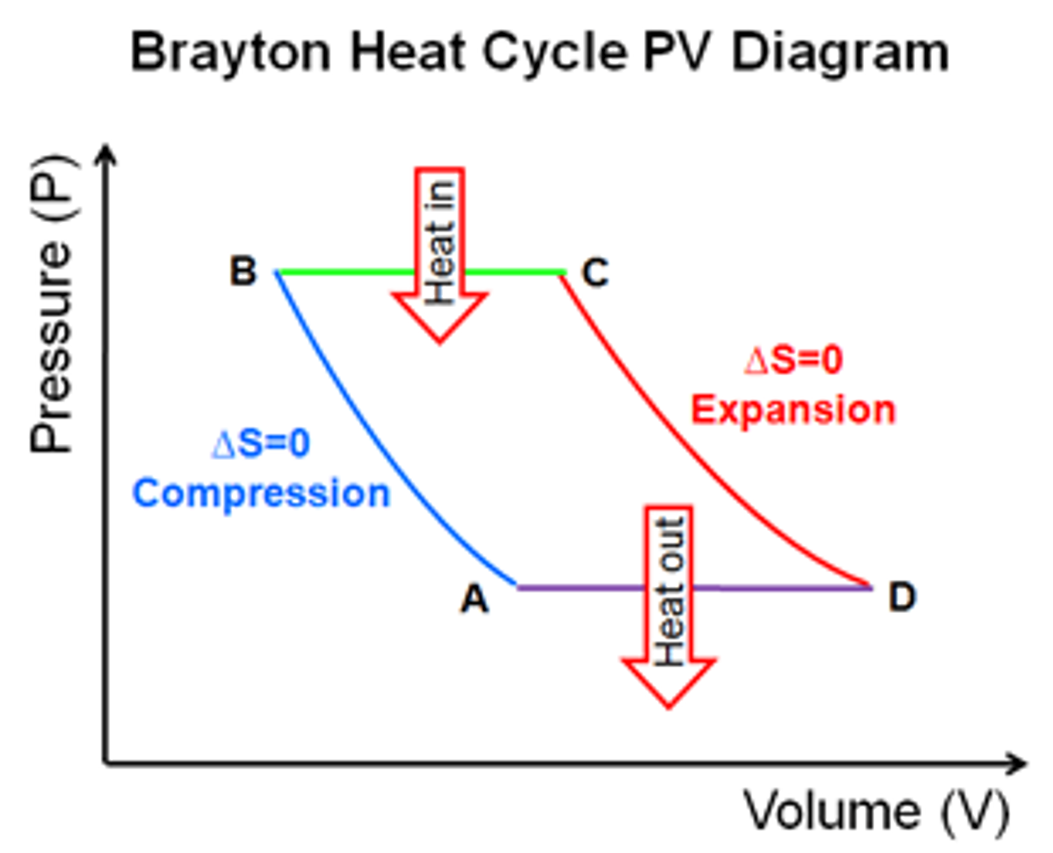
The p v diagram for the ideal brayton cycle is shown here. Brayton cycle is named after george brayton an american engineer who developed it.
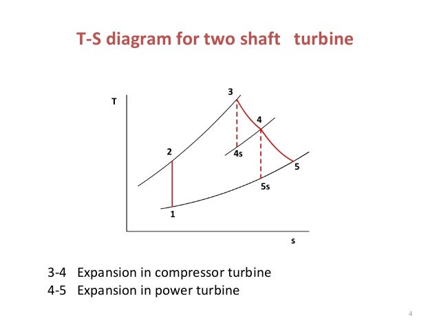
 8 Chapter Gas Power Cycles Ppt Video Online Download
Gas turbines are used to generate power at many places.

Brayton cycle ts diagram. Below are p v and t s diagrams of the brayton or joule cycle. Brayton cycle ts diagram when plotted on a pressure volume diagram the isobaric processes follow the isobaric lines for the gas the horizontal lines adiabatic processes move between these horizontal lines and the area bounded by the complete cycle path represents the total work that can be done during one cycle. When plotted on a pressure volume diagram the isobaric processes follow the isobaric lines for the gas the horizontal lines adiabatic processes move between these horizontal lines and the area bounded by the complete cycle path represents the total work that can be done during one cycle.
Thus the temperature rise in the combustion step is a factor of the ratio of specific heats higher than in the brayton cycle. Brayton cycle or joule cycle is a thermodynamic cycle upon which a gas turbine works. Learn how to draw the pv and ts diagram of brayton cycle.
The p v and t s diagrams of an ideal brayton cycle are shown on the left. Brayton cycle ts diagram. The heat is added at constant volume instead of constant pressure.
Q in h 3 h 2 c p t 3 t 2 heat is rejected at a constant pressure process process 4 1. Skip navigation sign in. You wont find the humphrey cycle in your thermo book.
The area under the t s diagram is proportional to the useful work and thrust generated by the engine. Diesel cycle p v diagram and the t s diagram. Learn how to draw the pv and ts diagram of brayton cycle.
Brayton cycle p v diagram and the t s diagram. The brayton cycle is a thermodynamic cycle named after george brayton that describes the workings of a constant pressure heat engine. In an ideal brayton cycle heat is added to the cycle at a constant pressure process process 2 3.
The original brayton engines used a piston compressor and piston expander but more modern gas turbine engines and airbreathing jet engines also follow the brayton cycle. The brayton cycle analysis is used to predict the thermodynamic performance of gas turbine engines. It involves a slight in theory modification to the brayton cycle.
This video is unavailable. Brayton cycle or air power cycle is employed in jet engines of aircrafts and aeroplanes brayton cycle pv ts diagram joule cyclebrayton cycle pv diagram. From the above graphs we can observe that the isentropic expansion of the diesel cycle is further extended in the brayton cycle to increase the cycle efficiency.
 Thermodynamics Ebook Brayton Cycle
Brayton Cycle Pv Ts Diagram
 Thermodynamics Ebook Brayton Cycle
 Gas Turbine Power Plant Regeneration Reheating Intercooling
 Air T S Diagram Catalogue Of Schemas
 Brayton Cycle Pv Ts Diagram
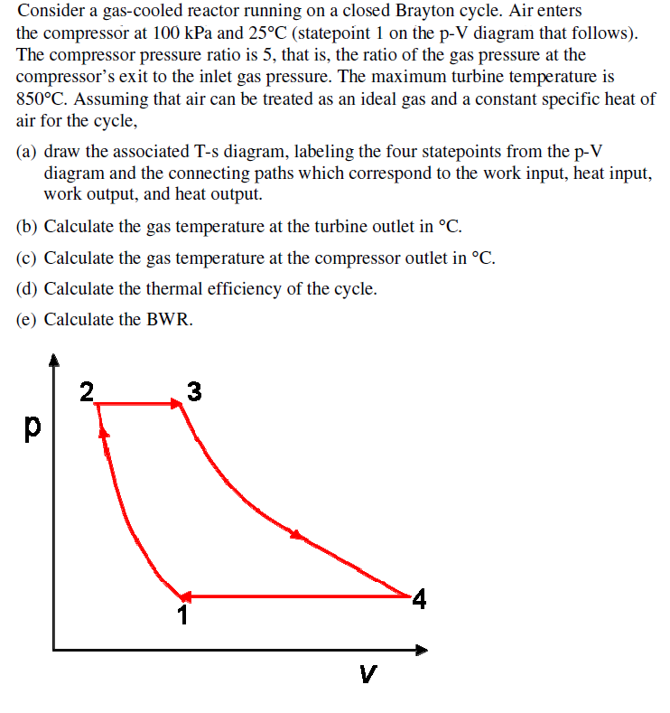 Solved Consider A Gas Cooled Reactor Running On A Closed
 Reversed Brayton Cycle Pv Diagram Bookmark About Wiring
 Air Refrigerator Working On Bell Coleman Cycle With Pv And
 Turbine Engine Thermodynamic Cycle Brayton Cycle
 Reversed Brayton Cycle Pv Diagram Numerical On Bell
 Turbine Engine Thermodynamic Cycle Brayton Cycle
 3 Presentation An Idealized Process In P V And T S Diagrams
 Gas Turbine Pv Diagram Group Electrical Schemes

 T S Diagram Of A Brayton Cycle With Regeneration In Gas
 Air T S Diagram Catalogue Of Schemas
 T S Diagram Turbine Catalogue Of Schemas
 Reversed Brayton Cycle Pv Diagram Bookmark About Wiring
 Effect Of Intercooling On Brayton Cycle Mechanical
 Pinterest Pinterest
 Reversed Brayton Cycle Pv Diagram Wiring Diagram Schematics
 Ch9 Lesson E Page 13 Deviations From The Ideal As
Belum ada Komentar untuk "Brayton Cycle Ts Diagram"
Posting Komentar