Heat Pump Ts Diagram
Thermodynamic heat pump cycles or refrigeration cycles are the conceptual and mathematical models for heat pumps and refrigerators. Always refer to your thermostat or equipment.
 T S Diagram Of The Improved Model Heat Pump Cycle For R134a
The ts diagram shows an ideal double cascade system using the same refrigerant in each loop.

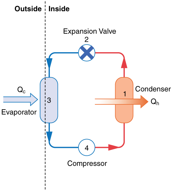
Heat pump ts diagram. It is a useful and common tool particularly because it helps to visualize the heat transfer during a process. In this case heat in the amount of q l is received by the gas from a heat sink and heat in the amount of q h is rejected to a heat source and a work input of w netin is required to accomplish the cycle. How is the heat supplied to the heat pump.
This diagram is to be used as reference for the low voltage control wiring of your heating and ac system. Are all heat pump systems the same. How do you calculate the heat supplied to the water by the heat pump.
Describe what happens in the vaporizer. Describe what happens in the condensor liquefier. As shown in the diagram you will need to power up the thermostat and the 24v ac power is connected to the r and c terminals.
The p v diagram of the reversed carnot cycle is shown on the left. A temperatureentropy diagram or ts diagram is a thermodynamic diagram used in thermodynamics to visualize changes to temperature and specific entropy during a thermodynamic process or cycle as the graph of a curve. September 12 201 general information warning.
There are many different types of heat pumps and are classified by the jobs they are to do as well as how they are designed to do these jobs. Provides the heat input to the evaporator of a high temperature cycle eg 2 units in series normally a different refrigerant would be used in each separate cycle in order to match the desired ranges of t p. The carnot refrigerator and heat pump.
For example heat pumps can be used to heat or cool water air or other fluids. Heat pump wiring diagrams created date. Give the coefficient of performance of the carnot process.
Heat pump thermostat wiring a typical wire color and terminal diagram. A heat pump is a mechanical system that allows for the transference of heat from one location the source at a lower temperature to another location the sink or heat sink at a higher temperature. To avoid the release of refrigerant into the atmosphere the refrigerant circuit of this unit must be serviced only by technicians who meet local state and federal proficiency.
Ac heat pump with single stage gas furnace and all fuel kit control wiring heat pump. Simplified piping diagram of a heat pump swimming pool heater. C is known as the common terminal.
What is happening in the expansion valve. 4 climatemaster water source heat pumps climatemaster water source heat pumps tranuility 20 ts series rev. The color of wire r is usually red and c is black.
These two connections will ensure that there is power to the thermostat that you are operating. A heat pump is a device that transfers heat energy from a source of heat to a destination called a heat sink. A collection of heat pump diagrams are available in the following printable diagramsthe images that we have collected below show the illustrations on how to make a heat pump installation wiring and work.
Why Is Carnot Cycle Not Possible In Heat Pump And
 Carnot Cycle Pv Ts Diagram Nuclear Power
 Illustration Of Heat Pump And The Thermodynamic Cycle On The
 Rankine Cycle Wikipedia
 Ch10 Lesson D Page 3 Carnot Heat Pump Cycle
 T S Diagram R22 Catalogue Of Schemas
 T S Diagram Boiler Wiring Diagram Document Guide
 Heat Engine Heat Engine Ts Diagram
 Heat Pump And Refrigeration Cycle Wikipedia

 A Heat Pump With Refrigerant 134a As The Working Fluid Is
 T S Diagram Wiring Diagram
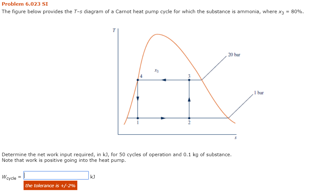 Solved Problem 6 023 Si The Figure Below Provides The T S
 Cheme 260 Heat Pump Systems Gas Refrigeration Systems May 31
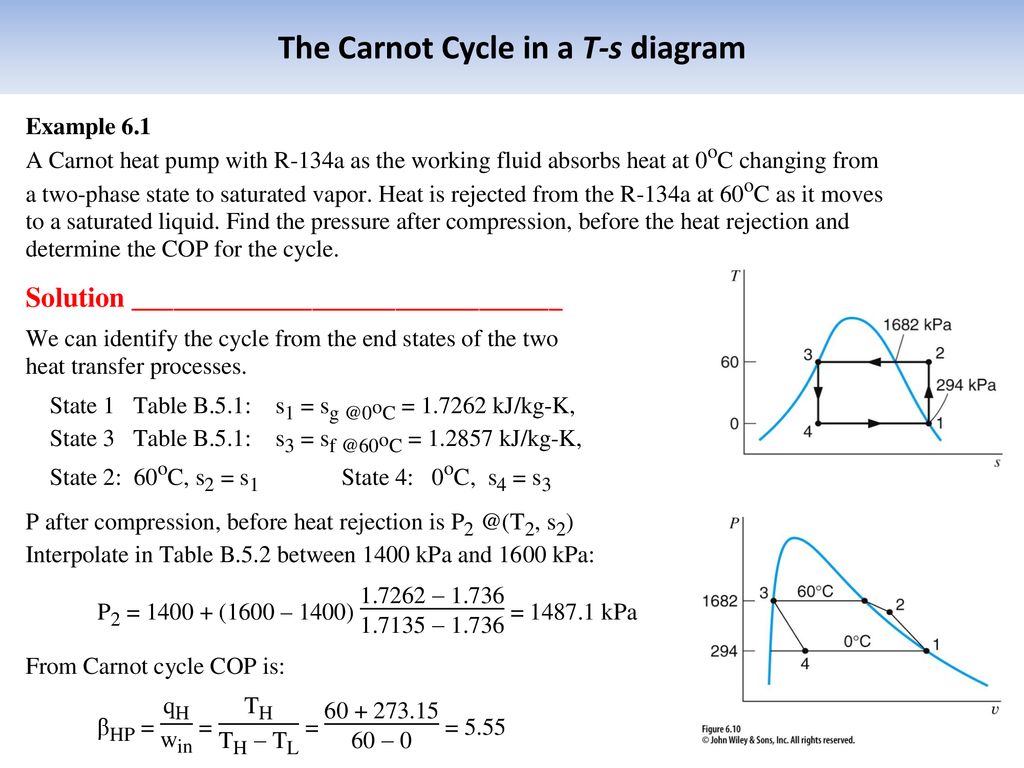 Lectures In Thermodynamics Claus Borgnakke Chapter 6 Ppt
 T S Diagram Boiler Wiring Diagram
 47 Principle Of A Mechanical Vapor Recompression Heat Pump
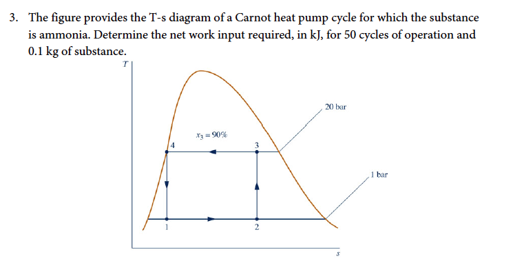 Solved The Figure Provides The T S Diagram Of A Carnot He
 Figure 11 From Waste Heat Recovery In Heat Pump Systems
 T S Diagram Of A Generalized Irreversible Carnot Type Heat
 T S Diagram Of A Generalized Irreversible Carnot Type Heat
 Applications Of Thermodynamics Heat Pumps And Refrigerators
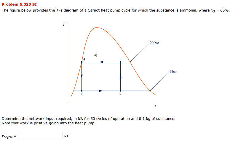 Solved Problem 6 023 Si The Figure Below Provides The T S
 T S Diagram Boiler Wiring Diagram Document Guide
 Ts Diagram Steam Production Wiring Diagram Document Guide
 Solved The T S Diagram For A Vapor Compression Heat Pump
Belum ada Komentar untuk "Heat Pump Ts Diagram"
Posting Komentar