Battery Combiner Wiring Diagram
This means that you can install a combiner at a later date if you wish. A remote parallel switch or push button can located on the.

In this example there are twin engines each with their own starting battery and one house bank for auxiliary loads.

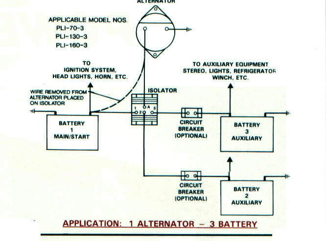
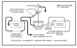
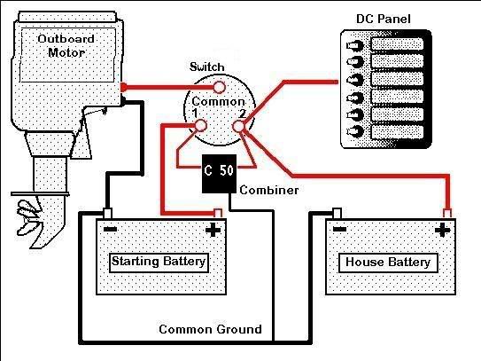
Battery combiner wiring diagram. When you first start the battery voltage is below the combiner switching level of about 13 volts so the combiner doesnt close until the battery has received enough charge to reach this voltage. The following wiring diagram shows how combiner 50s can be daisy chained to add extra banks. When a battery combiner senses a charge on a battery bank a in diagram it combines the battery banks to share the charge.
Cyrix battery combiners are an excellent replacement for diode isolators. Use parallel wiring to increase current power. The main feature is that there is virtually no voltage loss so that the output voltage of alternators or battery chargers does not need to be increased.
The combiner detects that charging is present by measuring the voltage on the battery that is receiving the charge. Since there is no way to de energize the wires lead ing between the battery combiner and the batteries you should. Battery wiring diagrams the following diagrams illustrate how to get increased current more power by using parallel wiring and how to increase voltage levels by using series wiring.
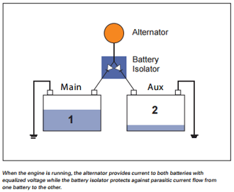
System schematics victron energy chinese czech dansk deutsch english espanol finnish francais greek hungarian italiano nederlands norsk polish portuguese romanian russian slovene swedish turkish home. Prioritising the starter battery in a typical setup the alternator is directly connected to the starter battery. One manufacturer blue sea systems sells a kit called add a battery which consists of a e h type switch and a combiner.
You can do both using series and parallel wiring in combinations. The battery combiner is wired directly to your batteries using at least 3 of the gauge wire specified by each battery combiner. Either engine can be started from either starting battery or both in parallel.
1 both 2 battery switch and two similar batteries or battery banks. If the combined battery banks require more current than the charger can deliver there will be a net discharge in the system b in diagram. If you study the diagram you will see that this circuit is identical to the basic two battery setup with the addition of a combiner.
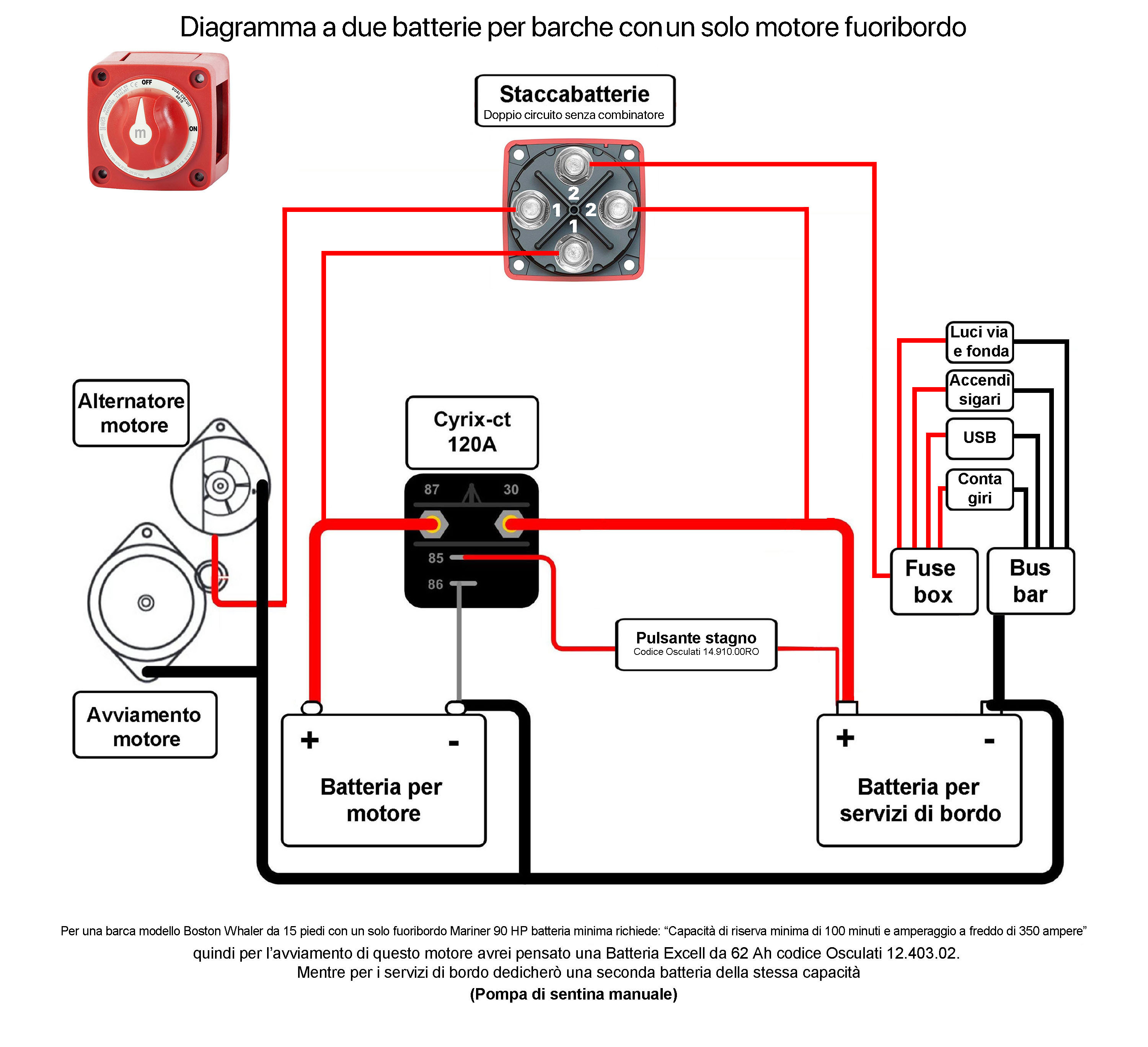 Cyrix Ct 120a Connection Diagram With Dual Battery Switch
 Diagram Guest Battery Combiner Wiring Diagram Full Version
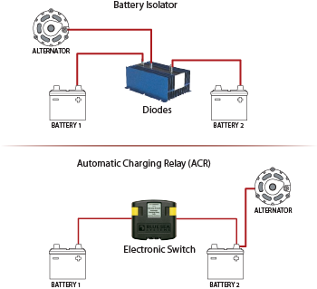

 Why Do I Need A Battery Isolator
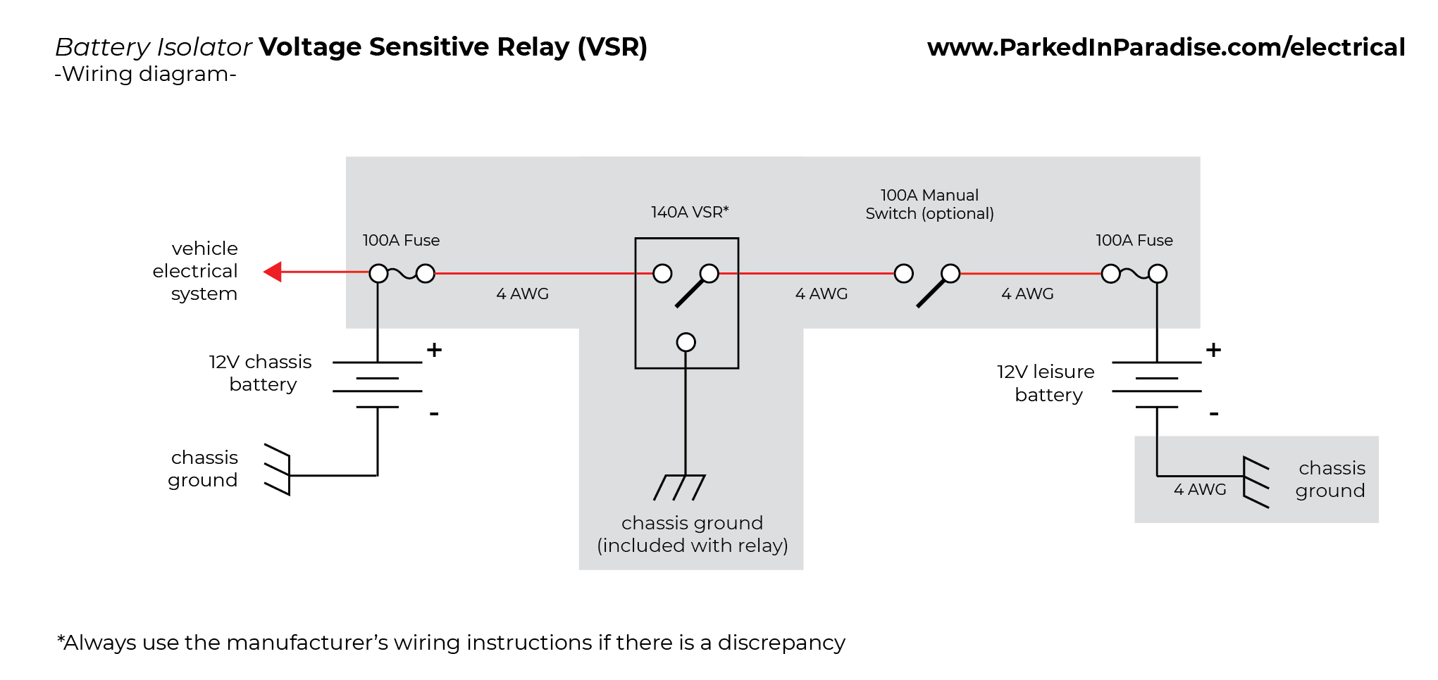
 Jaycorp Dual Battery Isolation Kit With 140a Smart Battery Isolator Vsr Voltage Sensitive Relay
Dual Battery Wiring Help Teamtalk


 How To Install A Battery Isolator In Your Conversion Van
 Victron Energy Argofet 100 Amp Diode Battery Isolator For Three Batteries
 Battery Isolators E Marine Systems
 Battery Isolators Vs Separators What S The Difference
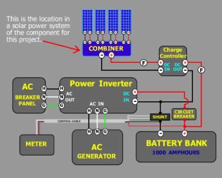
 Battery Combiner For 2 Mixed 48v Banks Northernarizona
 How To Add A Remote Battery Bank On A Boat

Hellroaring Battery Isolator Combiners Pirate4x4 Com
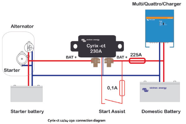 Cyrix Ct 12 24v 230a Battery Combiner

 Battery Isolators And Automatic Charging Relays Blue Sea
 Guest Battery Combiner Wiring Diagram
 Marine Battery Isolator Wiring Diagram Schematics Online
 Wiring Diagram For Battery Isolator Etrailer Com
 Typical Battery Isolator Circuits Arco
 Battery Management Wiring Schematics For Typical
Belum ada Komentar untuk "Battery Combiner Wiring Diagram"
Posting Komentar