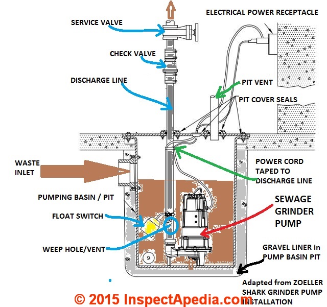
Septic Pump Wiring Diagram
Septic system lift pump and the float switch electrical question. A wiring diagram is an easy visual representation of the physical connections and physical layout associated with an electrical system or circuit.
Sump Pump Wiring Diagram Wiring Diagram
One wire provides power to the pump while the other wire is reserved for the septic pump alarm circuit.
Septic pump wiring diagram. There will normally be separate wires for the pump controls. It shows the parts of the circuit as simplified forms and also the power and also signal links between the devices. In this article we will discuss the correct way to hard wire a float switch to a submersible pump in order to achieve automatic operation.
Septic pump float switch wiring diagram what is a wiring diagram. It shows the components of the circuit as simplified shapes as well as the power as well as signal links between the tools. Septic system installers bury two wires from the house to a new septic tank.
I recently re wired a receptacle for the lift pump for my septic system. The float switch moves with the water level in the tank and this determines when the pump turns on and shuts off. A wiring diagram is a streamlined conventional photographic depiction of an electrical circuit.
A first take a look at a circuit representation might be complex yet if you can check out a metro map you can review schematics. The previous home owner had buried the cable under ground and the over the years the cable deteriorated and corroded and eventually shorted out. Septic pump float switch wiring diagram assortment of septic pump float switch wiring diagram.
Assortment of septic pump wiring diagram. A wiring diagram is a simplified traditional photographic representation of an electric circuit. Septic system installers install the alarm float switch to the inside of the septic tank.
Literally a circuit is the course that enables electrical energy to. Septic pump float switch wiring diagram a novice s overview of circuit diagrams. The pump will be controlled by a float or other switch which will activate the pump when the water reaches a pre set depth.
Submersible pumps use float switches to perform automatic operation. Route the plug wire from the septic tank pump up and out of the tank to the new electrical box. Obtaining from factor a to direct b.
Septic Tank Electrical Wiring Diagram New Us06462666
 Pump Float Switch Wiring Diagram With Blueprint Images
Bunch Ideas Of Bilge Pump Float Switch Wiring Diagram
Septic Tank Pump Wiring Diagram Wiring Diagrams List
Flygt Float Switch Seekingcommonground Org
 Septic Tank Wiring Schematic Wiring Diagram
Diagram Of Septic Tank Pdgroup Co
Septic Tank Pump Wiring Diagram Wiring Diagrams List
Sump Pump For Septic Tank Moneyrabbit Info
 Outside Sewer Hydromatic Sump Pump Systems Diagrams Wiring
Septic Tank Float Switch Installation With Level Wiring
Wiring Diagram For Septic Pump Wiring Diagram Schematics
Wiring Diagram For Septic Pump Wiring Diagram Schematics
Septic Pump Wiring Schematic Wiring Diagram
Hoot Sewer System Septic Wiring Diagram Paper Timer Diagrams
 Septic Pump Installation Guide
Elegant Septic Alarm Wiring Diagram For Related Post 56
Septic Tank Pump Float Switch Problems Eventsandmore
Septic Tank Alarm Troubleshooting Fubits Co
Wiring Diagram Septic Tank Control Schematics Online
Flygt Pumps Wiring Diagrams Educamaisvoce Com
 Find Out Here Sump Pump Float Switch Wiring Diagram Sample
 Schematic Septic Floats Catalogue Of Schemas
Septic Tank Effluent Pump System Ignitefilms Co
Belum ada Komentar untuk "Septic Pump Wiring Diagram"
Posting Komentar