Water Well Pressure Tank Diagram
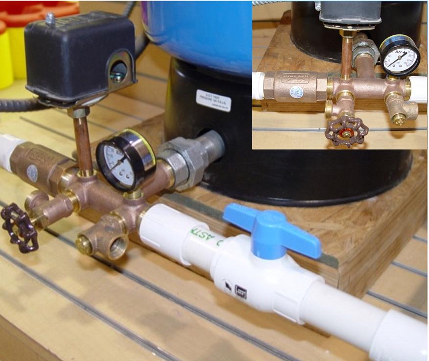
How to wire up a well water pressure switch. Taps are provided to accept pressure switch pressure gauge drain valve relief valve sniffer valve etc.
 Pressure Tank Schematic Wiring Diagram Directory
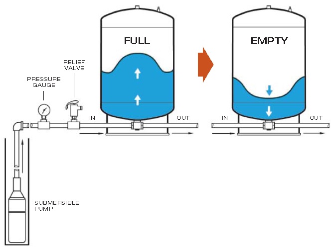
Drain valve drain easy draining of the system.

Water well pressure tank diagram. This well tank is designed and intended for cold ambient temperature water storage at a maximum pressure of 100 psig or 125 psig depending on your tank model any use other than with. Diaphragm well tank safety instructions installation warranty vertical series. Water well pressure tank diagrams thanks for visiting our site this is images about water well pressure tank diagrams posted by brenda botha in wiring category on sep 19 2019.
Diaphragm bladder tanks with permanent separation between the air and water. Find quality pressure tanks online or in store. Pressure tanks provide storage for your water system.
There are three general types of water storage tanks. Well pump pressure tank diagram 1. You can also find other images like wiring diagram parts diagram replacement parts electrical diagram repair manuals engine diagram engine scheme wiring harness fuse box vacuum diagram timing belt timing.
Place tank in desired location and level it. As water is used the pressure in the tank decreases. When the pressure falls to 40 psi the switch energizes the pump circuit and the cycle repeats itself.
Notice the tank tee assembly is a quick and compact way to install the tank while incorporating a nipple union a recommended check valve pressure switch pressure gauge pop off valve and a faucet to get emergency water out ot the system even if the water is turned off to the house by the ball valve nearby. Water storage at a maximum pressure of 100 psig any use other than with cold water or at a sustained or instantaneous pressure in excess. When the tank reaches its peak pressure typically at 60 pounds per square inch the switch cuts the electrical power to the water pump.
Tank tee connets water line from pump to pressure tank and service line from tank to house. Tanks with a float or water separating the air from the water not used in recent years plain steel tanks each kind of tank serves a specific purpose. Relief valve protects against pressure build up.
Basic overview of a well water system and how it works with a softener and conditioning filter showing all the well components good for new homeowners who want to understand the components of.
 Well Pressure Tank Installation Diagram Well Pressure Tank

 Waterlogged Well Water Pressure Tank Definition Water


 Pin On Well Pump House


 Pressure Tanks Plumbing In 2019 Plumbing Shallow Well


 Pin By Tina Edinger On Water Wells Pump House Water Well


Belum ada Komentar untuk "Water Well Pressure Tank Diagram"
Posting Komentar