Sump Pump Control Panel Wiring Diagram
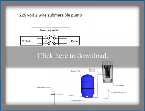
A submersible pump can be either two or three wire regardless of the voltage coming from the panel so start at your pump and follow the conduit back. Systematic diagrams for control switched panel.
 Sump Pump Control Wiring Diagram Wiring Diagrams Folder
A wiring diagram is a kind of schematic which makes use of abstract photographic signs to show all the interconnections of components in a system.

Sump pump control panel wiring diagram. Sump pump control wiring. A wiring diagram is a simplified standard photographic representation of an electric circuit. Switch and pilot light companies contacts us mail.
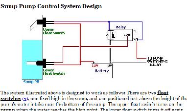
Switch bore hole pumping machine. The information below refers to 115v pumps and wiring. Well look at single and double switch arrangements and how to wire them and then look at equivalent circuits using kari series float switches.
Sump pump wiring diagram. Electrical diagram electrical wiring electric motor electrical engineering control panel power strip outlets electronic circuit woodworking. Sump pump control wiring in auto and manual to float switch.
Tank control one line. If the conduit runs into a control box before continuing to the water pressure switch chances are you have a three wire pump. These instructions and diagrams will serve to teach you the basics of float switch control.
Switch for submessible pumps circuit diagram. If it runs straight to the pressure switch it is a two wire. Sump pump electrical wiring power strip circuit engineering workshop projects electric atelier.
Panel must be ordered with the proper amp rating matching that of the pump. Today i am hear to write about submersible pump control box wiring diagram in this post you will complete understood about 3 wire submersible pump wiring diagram which is an single phase submersible pump motorwhy we called a single phase submersible motor a 3 wire submersible that we also know that we have two wire in single phase power supply. Not only a contactor but also i install the thermal overload relay which will protect the motor form burning in case of over current flow to the circuit.
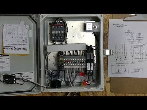
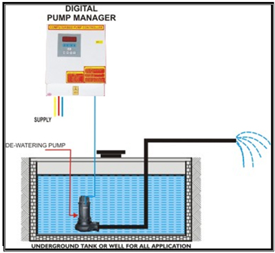
Available with many options and nema1 indoor and nema4x outdoor enclosures. Common applications include sump basins effluent or sewage pump chambers and lift stations. Do not use the method described below for 230v pumps.
Today i am here to share with you the 3 phase submersible pump wiring diagramin which i control a three phase submersible pump motor using magnetic contactor. Pump control panel wiring diagram schematic just whats wiring diagram. In this article we will discuss the correct way to hard wire a float switch to a submersible pump in order to achieve automatic operation.
Collection of sump pump control panel wiring diagram. Submersible pump control box wiring diagram for 3 wire single phase. We recommend using a piggy back float switch or control panel to operate 230v pumps.
Acorta tus urls y gana dinero. For reliable control of a single pump in residential or commercial installations. It reveals the components of the circuit as simplified shapes as well as the power and signal connections between the tools.
Were going to look at a progression of straightforward pump control arrangements using float switches.

 Sump Pump Control Wiring Diagram Unique Rule Bilge Pump

 Diy Sump Pump Control Circuit Dc12v
 Sump Pump Control Wiring Diagram Wiring Diagram Schematics
 Pump Panel Wiring Diagram International Electrical Diagram

 Wiring Diagram For 220 Volt Submersible Pump Wiring
 Sump Pump Control Panel Wiring Diagram All Diagram Schematics

 Float Switch Installation Wiring Control Diagrams Apg
 Sump Pump Wiring Diagram Wiring Diagram
 Sim A Single Phase Simplex Sump Pump Control Panel See
 Wire Diagram Flygt Pump Wrg 8765 Flygt 3068 Wiring Diagram


 Fire Pump Control Panel Wiring Diagram Pdf What Are Jockey
 How To Wire An Orenco S Series Control Panel
 Submersible Well Pump Wiring Diagrams Lovetoknow
 Home Improvement Programme Opt Out Scheme Darwin Tampines
 Pump Control Schematic Group Electrical Schemes

 Fire Pump Control Panel Wiring Diagram Pdf What Are Jockey
 Float Switch Installation Wiring Control Diagrams Apg
Belum ada Komentar untuk "Sump Pump Control Panel Wiring Diagram"
Posting Komentar