Step Dimming Ballast Wiring Diagram
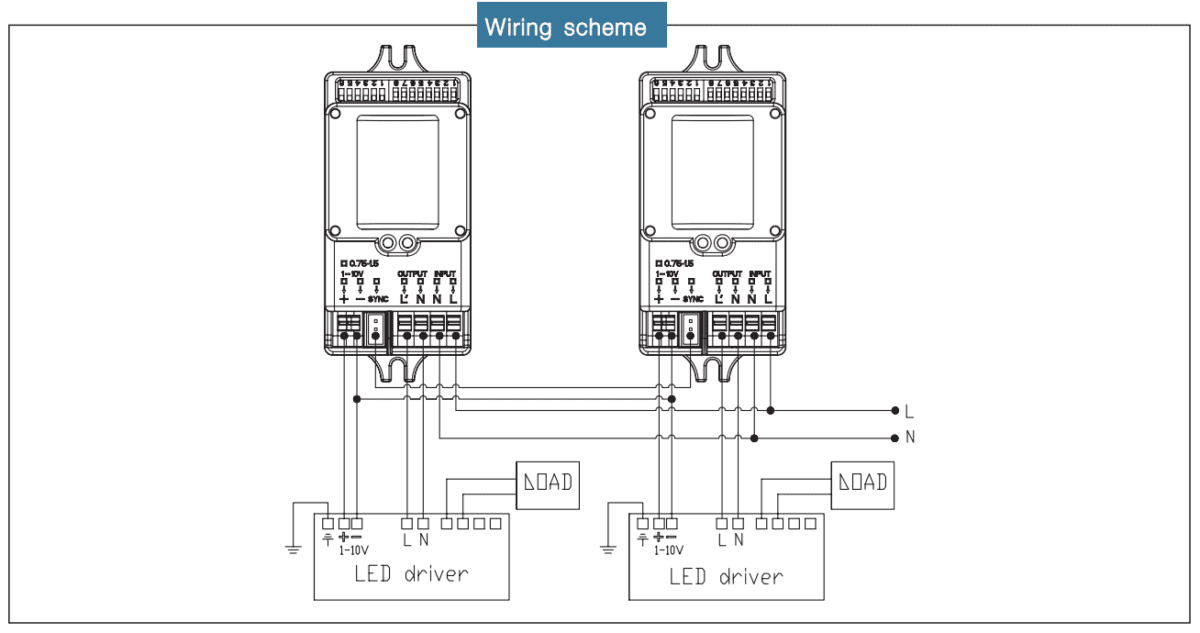
2 lamp dimming ballast wiring diagram. A typical 0 10v wiring diagram is shown below.
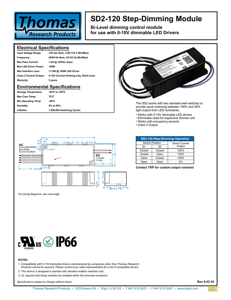 Sd2 120 Step Dimming Module
Occupancy sensor with 0 10v dimming control installation instructions.

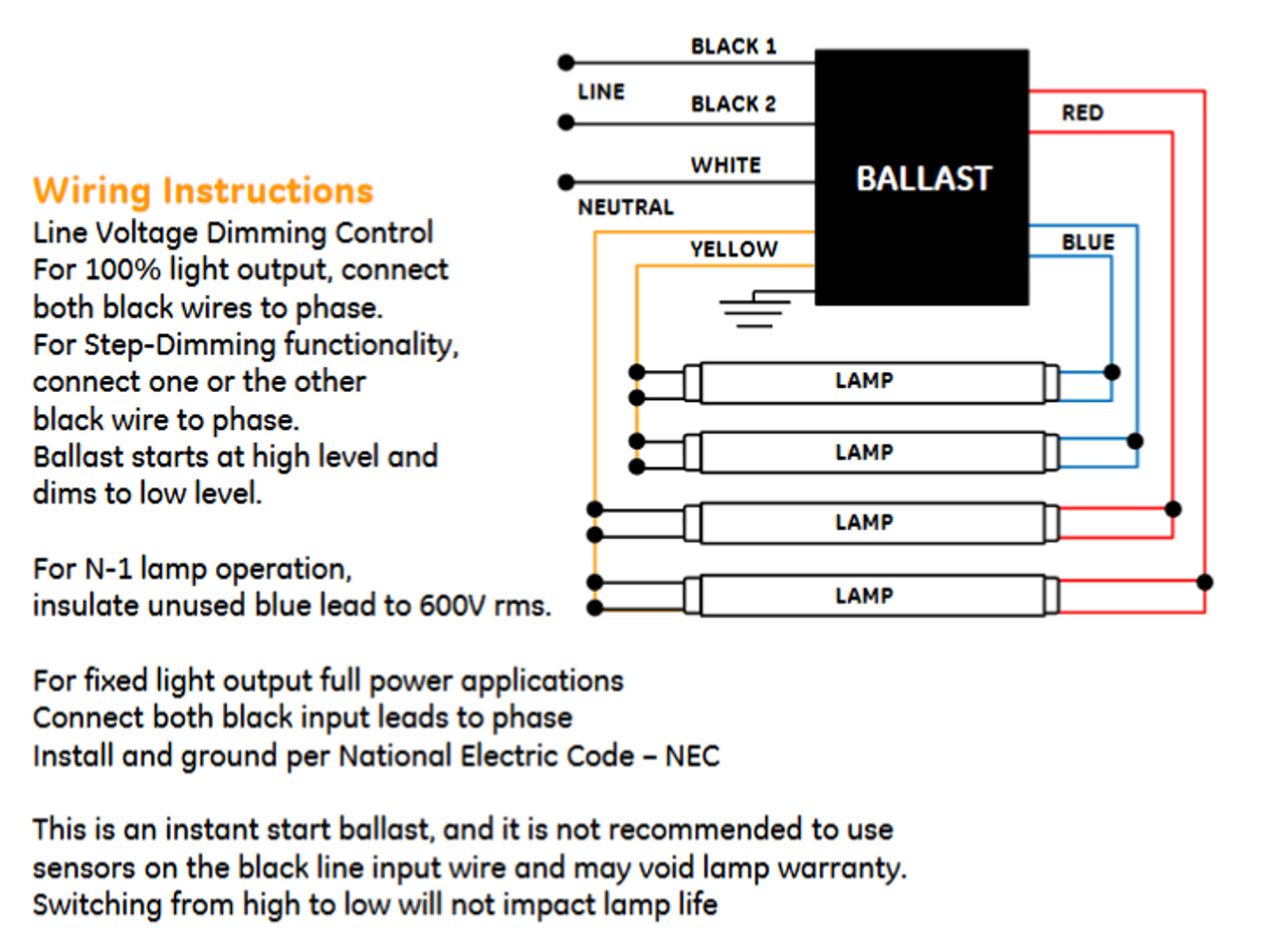
Step dimming ballast wiring diagram. Ge ultramax ballasts provide a wide variety t8 step dimming ballast. This irs2530d used to be applied in linear dimming ballast 3 way dimming ballast and multi level switch dimming ballast. Ge lfl ultramax step dimming electronic dimming ballast wiring instructions line voltage dimming control gray wire connected to line or neutral.
Search the lutron archive of wiring diagrams. Dimming ballasts are available for fluorescent tubes and cfls that use an external ballast. Attach sensor to fixture or electrical box using the 2 8.
To find a diagram for a specific product or system please use the drop down menus below. Dimming ballast functions and protects the circuit against line and load fault conditions. Quick easy troubleshooting.
How to install a dimmer. Step dimming control facilitates energy code compliance without installation of low voltage control wiring. Application note 28 appendix b.
13 sockets and lampholders 16 lamp wiring diagrams 19 ballast control types 20 ecosystem ballasts 22 emergency backup ballast 24 ballast troubleshooting 25 installation best practices 26 appendix a. Our standard 0 10v dimming driver option is often provided standard check spec sheets and dims down to 10 at minimum light level. The levelpro family of ballasts is designed for maximum energy savings and high efficiency and they are cee compliant.
Ge ultramax t8 bi level dimming ballasts 68049 012013 printed in usa. 2 lamp series ballast wiring. Dimming cfls and leds.
Using advance mark 7 or mark 10 dimming ballast and dimmer switch. These ballasts use two line voltage switches for selecting operation at full intensity or at half power. Step dimming ballasts are relatively inexpensive and often used with occupancyvacancy sensors or automatic timers to optimize energy usage.
Fluorescent dimming systems technical guide 02 lutron fluorescent dimming ballasts 04 how it works 05 lamp. Electrically connect the sensor to the lighting system per the applicable wiring diagram on page 4. View all legacy products systems.
0 10v or 4 wire dimming ballasts provide continuous light output typically 5 to 100 based on the input voltage of the 0 10v line. When used with program start ballast and led drivers a 1 2 second delay from occupancy detection to turn. These ballasts are usually rapid start or programmed start and have a good dimming range.
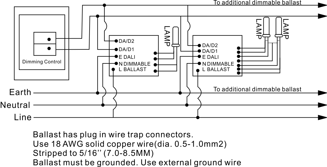
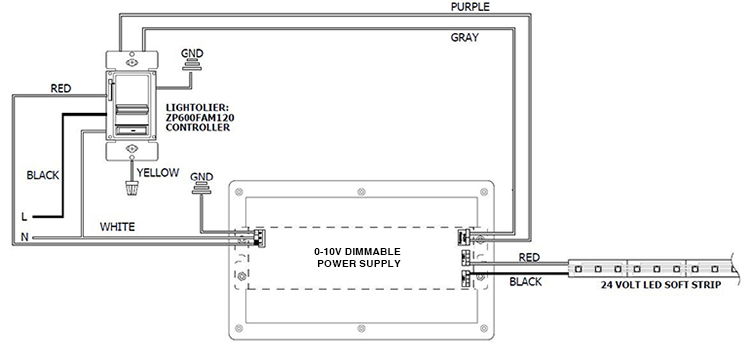
Below is the pin assignment function and datasheet of the irs2530d. 0 10v dimming wiring diagram 0 10v dimmer switch leviton ip710 lfz or equal for other types of dimming control systems consult controls manufacturer for wiring instructions switched hot black switched hot red typical low voltage dimming wires purple gray typical electrical panel hot black typical 120v or 277v 60 hz neutral white. Operates at 100 light level open circuit gray wire.
A 0 10v dimmer is considered analog dimming and all usai 0 10v dimming options are considered to be sink type dimming.
 Lutron Dimming Ballast Wiring Diagram Ehdt832mu210
 Ge Stepped Dimming Ballast Wiring Diagram Technical Diagrams


 Step Dimming Wiring Diagram List Of Wiring Diagrams
 How To Bypass A Ballast 1000bulbs Com
 Philips Advance Ballast Wiring Diagram Awesome 0 10v Dimming

 Dimming Ballast Wiring Diagramn Wiring Diagram

 Ge Ultramax Ge432max90 S60 73229 T8 Step Dimming Ballast
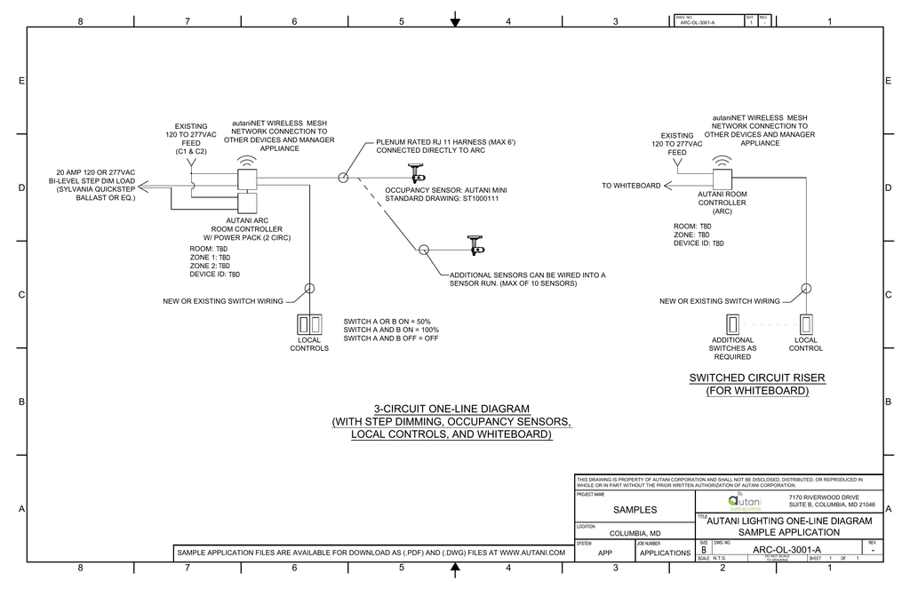 3 Circuit One Line Diagram With Step Dimming Occupancy Sensors

 How To Install Motion Sensor Light Full Guidelines
Dimmable Ballast Wiring Diagram Wiring Diagram Directory
 277v Ballast Wiring Wiring Diagrams Folder

 Step Dimming Wiring Diagram Wiring Diagram

 10v Dimmer Wiring Diagram Schematic
 0 10v Dimming Ballast Wiring Diagram Wiring Diagram

![]() Fluorescent With Dimmer Wiring Diagram Fluorescent Dimmer
Fluorescent With Dimmer Wiring Diagram Fluorescent Dimmer
 T8 Dimming Ballast Wiring Diagrams Wiring Diagram


 58 Good Thought Image Of T8 Dimming Ballast Wiring Diagram
 Hid Lamp Dimming Electrical Construction Maintenance
Belum ada Komentar untuk "Step Dimming Ballast Wiring Diagram"
Posting Komentar