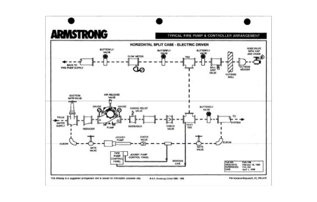
Fire Pump Installation Diagram
Sized to carry locked rotor currents of the fire pump motors jockey pump and associated fire pump accessory equipment. Cistern lake river or canal pump installation.
 Electric Fire Pump Schematic Data Wiring Schemes
As projects become larger and more complex such as those found in campus settings installation requirements vary and design options increase which often leads to confusion on the electrical design front.

Fire pump installation diagram. Fire pump sizing the estimated performance of the fire pump between 100 and 150 of rated flow can be calculated using the following formula. The ce code part i governs installation of various electrical equipment. When it comes to fire pumps theres more to designing and installing these units than meets the eye.
Find all fire pump controller drawings as well as jockey pump controller remote alarm panel and low suction shutdown controller drawings here. But in addition to the cec part i this type of electrical equipment must meet provisions of other important documents. Guide to the installation and operation of fire pumps 25.
Index of products. The conductor installation shall meet 6956b. Fire hazard unsatisfactory performance and equipment failure.
Options and miscellaneous. 21331 ec mod. Bailey line road 87631 views.
Ecv variable speed controller. Submersible well pump accessories installation diagram. Our first stop is the scope of.
Battery operated sump pump installation. Home technical information diagrams typical pump installations. A fire pump is certainly also covered by the code requirements.
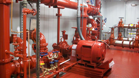
Occasionally we see an installation of new fire pump equipment which catches our eye in a good way that is the installing contractor did an exemplary job with installing the equipment. The proper installation of fire pumps and controls is covered in nfpa 20 as well as in nec article 695. Exception for on site generators with continuous rating over 225 of fire pump motor fla.
Lets check out these additional requirements. Fire pump controllers. Therefore its important to turn to more than art.
695 of the nec for. Y 07x 170 x flow expressed as a percentage of rated flow y pressure created by the pump net pressure expressed as a percent of rated pressure 93. Nfpa20 standard for the installation of stationary pumps for fire protection 2.
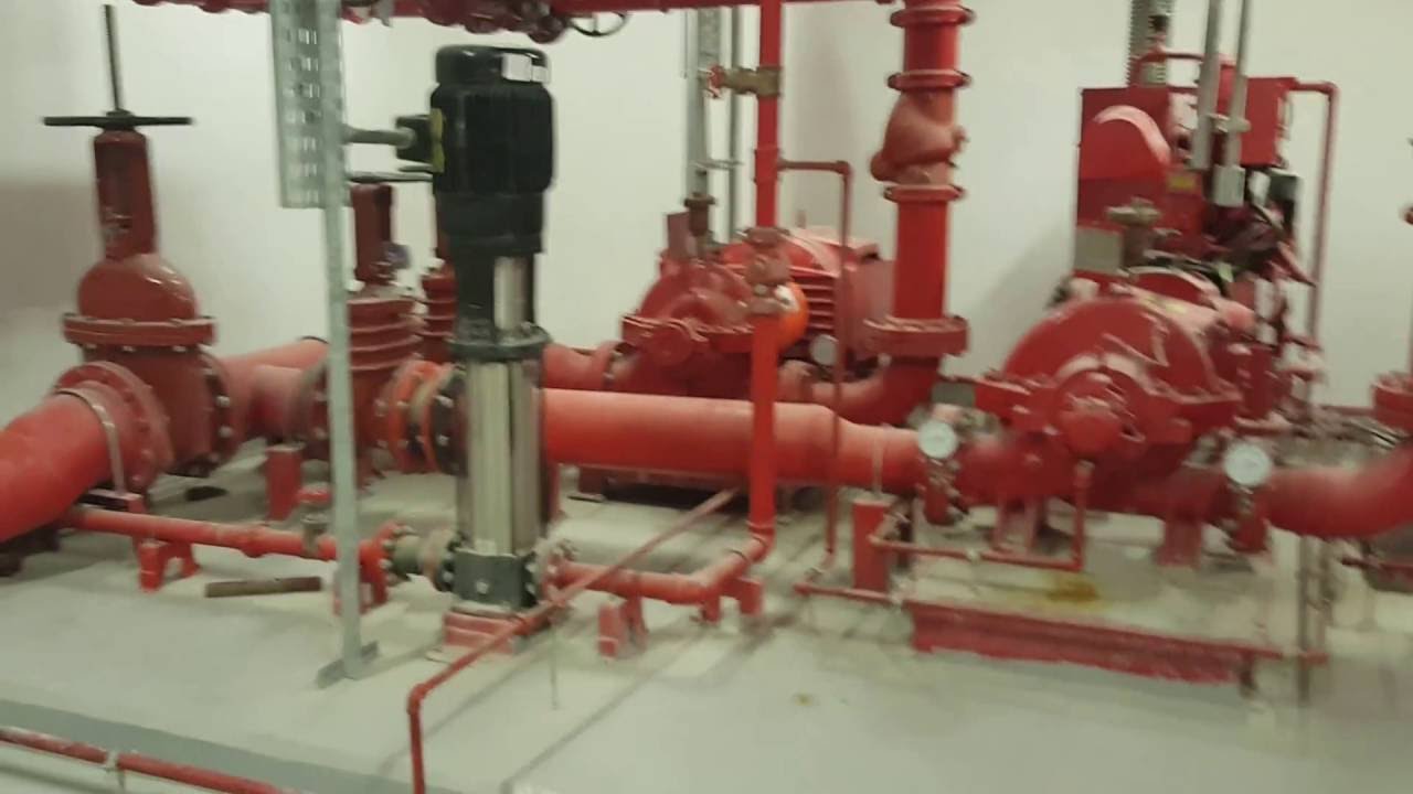
This diagram shows the main features of fire pump house installations these will vary depending upon the number and types of pumps to be installed and they will be placed to suit the position of main pipe runs etc. Purpose of a fire pump to protect lives and properties against fire by supplying an adequate water supply to automatic sprinklers or standpipe systems to meet building codes and insurance requirements 3. The overcurrent protection shall be sized at short circuit ratings nec 43052 or 2.
Choosing a backup generator plus 3 legal house connection options transfer switch and more duration.
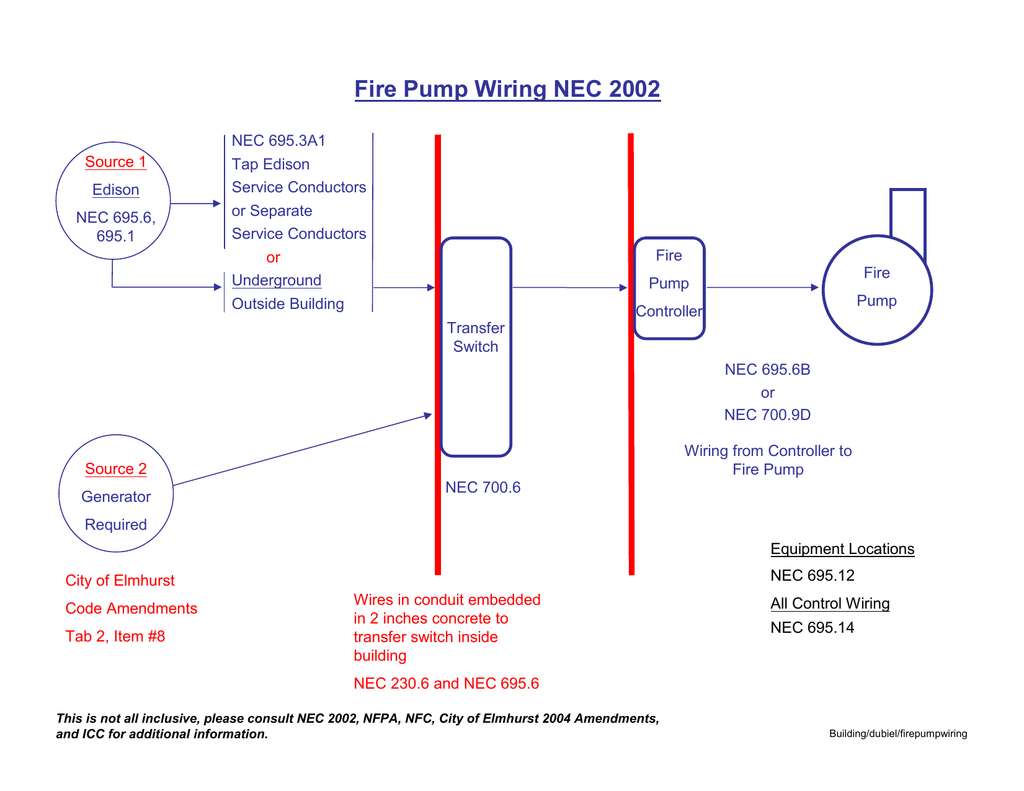 Fire Pump Wiring Code
Installation And Operation Instructions
 Nec Rules For Fire Pumps Electrical Construction
 Fire Pump Wiring Diagram Group Electrical Schemes
 Waterous Fire Pump Engine Diagram Wiring Library
 Electric Fire Pump Schematic Wiring Diagram
Electric Diesel Fire Pump Check List
 Wiring Diagram For Fire Pump

Fire Pump Installation Introduction Underground Pump Rooms
General Information Typical Pressure Sensing Line Connection

 Canariis Home
 Fire Pumps Installation Details
 Fire Pump Installation Diagram
 Fire Pump Functions The Main Function Of A Fire Pump Is To
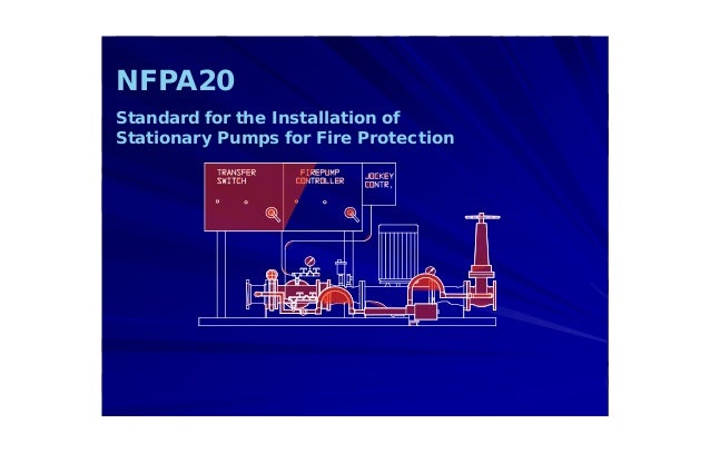 Nfpa20 Standard For The Installation Of Stationary Pumps For
 Fire Pump Wiring Diagram Wiring Diagram
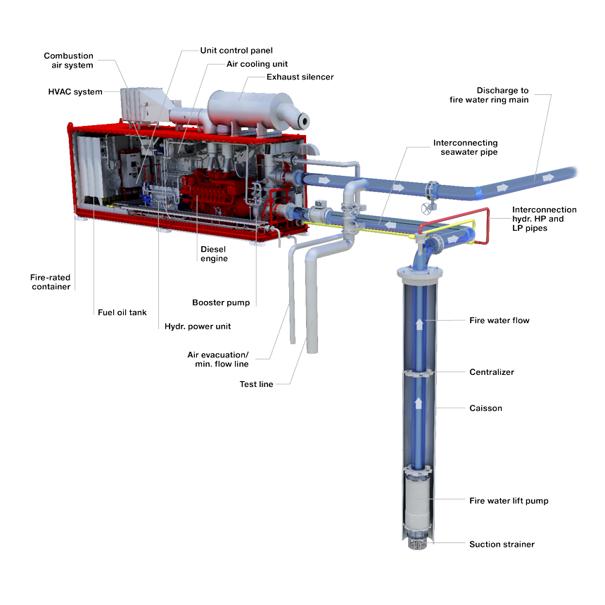 Framo Submersible Pumps Oil And Gas Pumping Systems
 Diesel Engine Fire Pump Controller Wiring Diagram Lovely

Nec Rules For Fire Pumps Electrical Construction
Electronic Foam Proportioning Systems Description
 Nfpa20 Standard For The Installation Of Stationary Pumps For
 Fire Pump Wiring Diagram Wiring Diagram
Belum ada Komentar untuk "Fire Pump Installation Diagram"
Posting Komentar