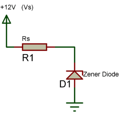
Zener Diode Circuit Diagram
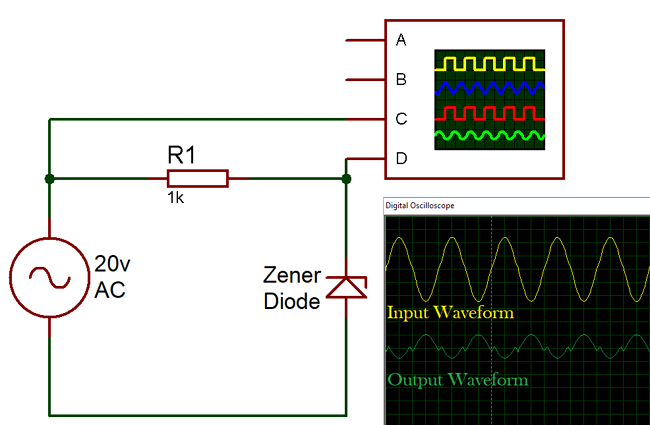
The reverse biasing means the n type material of the diode is connected to the positive terminal of the supply and the p type material is connected to the negative terminal of the supply. The circuit of figure below has two zeners connected series opposing to symmetrically clip a waveform at nearly the zener voltage.
 Zener Diode As Voltage Regulator Tutorial
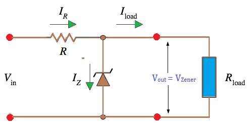
Resistor value ohms v1 v2 zener current load current the above diagram is of a shunt regulators because the regulating element is parallel to the load element.

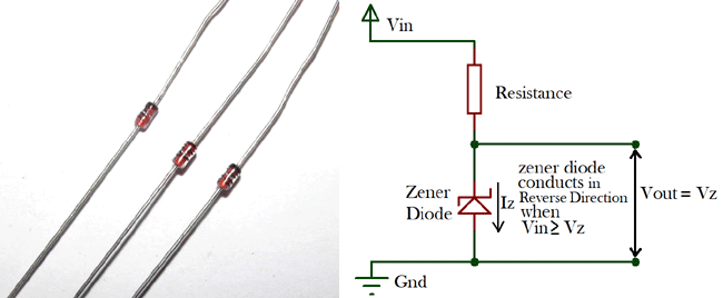
Zener diode circuit diagram. The zener diode is employed in reverse biasing. One more shape of zener diode circuit is overvoltage shield circuit. This semiconductor is manufactured in a wide variety of voltages and powers.
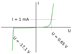
A clipping circuit which clips the peaks of waveform at approximately the zener voltage of the diodes. The zener diode is a type of diode which operates under the reverse bias that breakdowns when the applied voltage reaches a particular reverse bias voltage or knee voltage. Thank you and my name is emmanuel you can contact me through this number electronic is sweet ooooooooo.
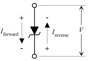
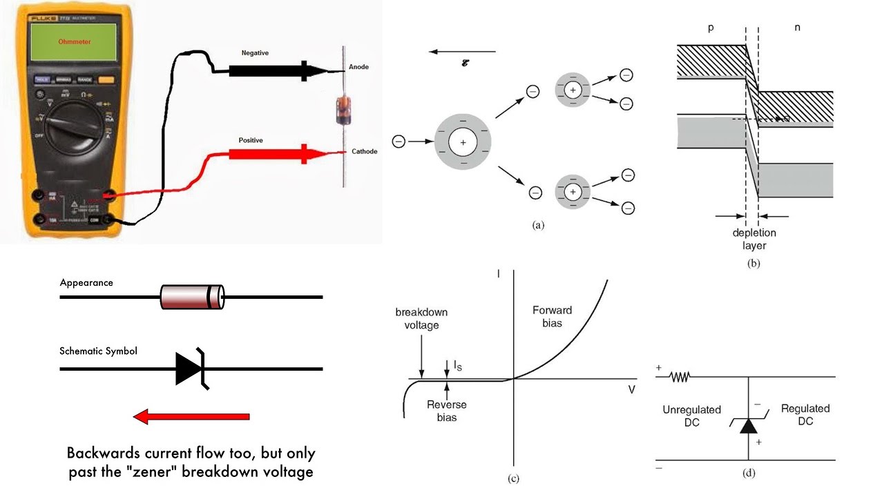
It allows the current to flow as like a normal pn junction diode when it is forward biased and block the reverse flow of current during the reverse bias up to the breakdown voltage. Another form of zener diode circuit is an overvoltage protection circuit. Zener diode voltage regulator circuit.
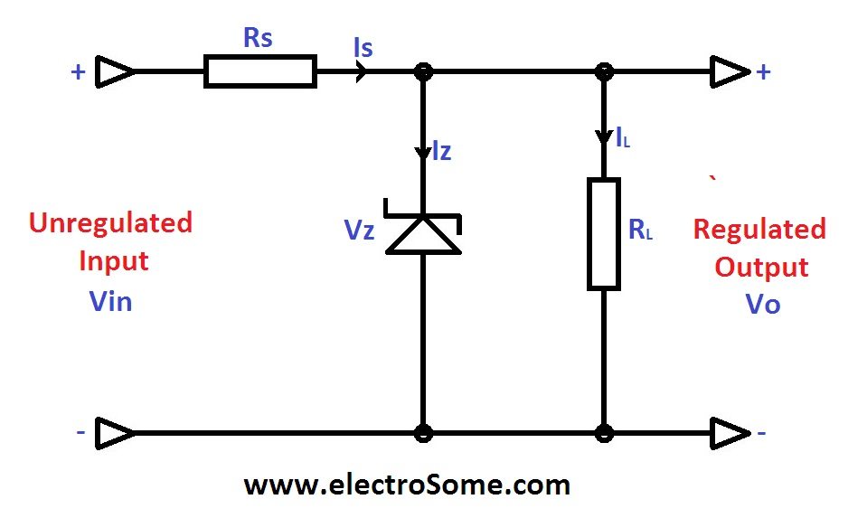
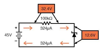
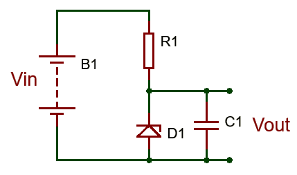
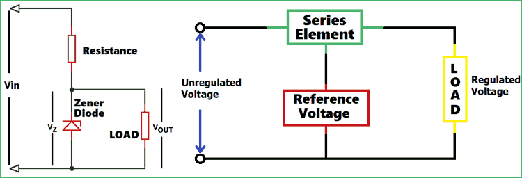
Zener diode voltage regulator circuit diagram in the above circuit diagram excess voltage vin vz will drop across rs thus by limiting the current through zener. For the proper designing of the regulator we should know unregulated input voltage range. This zener diode voltage regulator circuit uses a zener diode to establish a reference voltage.
The circuit diagram of the zener diode is shown in the figure below. When selecting zener diode voltage one should remember that emitter voltage will be lesser than zener voltage by an amount equal to base emitter voltige minus 06 volts for silicon transistor. This zener diode circuit uses the zener diode in a slightly different way detecting the breakdown current through the diode once a certain voltage has been reached.
The zener diode produces a stable reference voltage across the load which fulfills the criteria of regulator requirement. When connected in parallel with a variable voltage source so that it is reverse biased a zener diode conducts when the voltage reaches the diodes reverse breakdown voltage. Zener diodes have voltage values from less than 2 volts to several hundred volts and they can dissipate power ranging from 025 to 50 watts or more.
Zener diodes are widely used as voltage references and as shunt regulators to regulate the voltage across small circuits. Zener diode circuit to avoid overvoltage. Zener diode is a simple component to understand in a electronic components and it work normal in your circuit diagram the time you used it.
 Zener Diode Voltage Regulator
 Zener Diode Working With Circuit Diagram And Applications
 An Equivalent Circuit With Zener Diode If The External
 Zener Diode Voltage Regulator Zener Diode Application Note

 Zener Diode As A Voltage Regulator Elex Focus
 What Is Zener Diode Operation Principle Types Uses Of
 Zener Diode Wikipedia
 Characteristics Zener Diode Photodiode Solar Cell Light
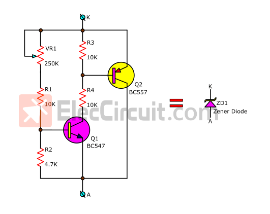 Variable Zener Diode Circuit Adjust Voltage Output
What Is The Actual Symbol For Zener Diode Quora

 Zener Diode And Filter Circuit Lets Learn Nepal
 Why Does Zener Diode Work In Reverse Bias Quora
 3 9v Zener Diode 1n4730a Pin Diagram Equivalent Datasheet
 What Are Zener Diodes Diodes And Rectifiers Electronics
 Zener Diode As Voltage Regulator Electrical Engineering
 What Is Zener Diode Operation Principle Types Uses Of
 Zener Diode Circuits Design Electronics Notes
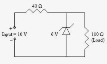
Circuit Analysis Voltage Across Zener Diode Electrical


 What Is A Zener Diode Zener Diode Circuit
 What Is Zener Diode Operation Principle Types Uses Of
 Voltage Regulator Circuits Linear Voltage Regulator Zener
Belum ada Komentar untuk "Zener Diode Circuit Diagram"
Posting Komentar