Fanuc Encoder Cable Diagram
If the fanuc motor has a red cap it is an ac motor. Fanuc cable wiring diagrams welcome thank you for visiting this simple website we are trying to improve this website the website is in the development stage support from you in any form really helps us we really appreciate that.
 Tosoku Hc115 Manual Pulse Generator Mpg 4 Axis Hand Wheel
Led d2 green indicates the converter has power.

Fanuc encoder cable diagram. P1 is the output of quadrature encoder signals and commutation signals. Browse by manufacturer get. The angular position of the resolver stator to the resolver rotor is critical.
We will share this website for you articles and images of wiring diagrams engine schemes engine problems engine diagrams transmission diagrams replacement parts fuses electrical diagrams repair manuals wiring harnesses fuse boxes vacuum diagrams. 25 pin male 8 pin modular phonefemale hmi cab c84a 8 pin modular phonemale. If the fanuc motor has a yellow or black end cap it is a dc motor.
A single channel encoder often called a tachometer is normally used in systems that rotate in one direction only and require simple position and velocity information. Page 6 of 80. The hmi cab c84a cable drawing is proprietary information and is provided for reference only.
You can also find other images like wiring diagram parts diagram replacement parts electrical diagram repair manuals engine diagram engine scheme wiring harness fuse box vacuum diagram timing belt timing chain brakes diagram transmission diagram and engine problems. Encoder cable for fanuc datasheet cross reference circuit and application notes in pdf format. Most resolver stators are mounted in a way that they can be rotated 360 degrees easily in relation to the motor housing with no alignment pin or key.
You can also find other images like parts wiring diagram parts parts diagram parts replacement parts parts electrical diagram parts repair manuals parts engine diagram parts engine scheme diagram parts wiring harness diagram parts fuse box diagram parts vacuum diagram parts timing belt diagram parts timing chain. The circuit also provides network control. Fanuc serial encoder converter connector pinout.
The rs232 to rs422 circuit board is contained in the 25 pin d shell. Fanuc servo motor wiring diagram you are welcome to our site this is images about fanuc servo motor wiring diagram posted by brenda botha in wiring category on aug 25 2019. Fanuc cable wiring diagrams you are welcome to our site this is images about fanuc cable wiring diagrams posted by alice ferreira in fanuc category on sep 15 2019.
P2 is the serial encoder input. The first step in retrofitting a motor to find your motor in our motor compatibility tables listed on the following pages. Led d1 red indicates the converter is not receiving a valid signal from the encoder.
Incremental encoders are available in two basic output types single channel and quadrature. Quadrature encoders have dual channels a and b phased 90 electrical degrees apart. Samples of fanuc motor labels are shown in appendix to help identify your motor.
E69 c06b ladder diagram for encoder cpm1a ladder e6b2 cwz6c plc connect encoder plc based water level control ladder diagram omron ladder diagram e69 c10m e69 c10b e69 c04b. Precision machine tool corporation 10110 south 54th street franklin wi 53132 4144235500. The cable is licensed from allen bradley and cannot be modified.


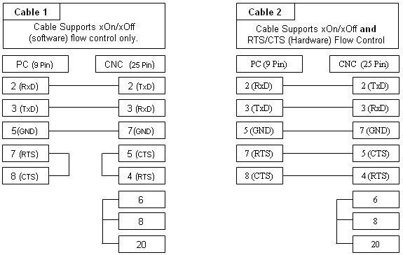
 Fanuc Rs232 Troubleshooting Cable Drawings And Settings

Centroid Fanuc Cnc Retrofit Installation Manual Cnc Retrofits
 Fanuc Cable Wiring Diagrams Wiring Diagram
 Fanuc Cable Wiring Diagrams Wiring Diagram

 Fanuc Feedback Cable Fanuc Power Cable Manufacturer From

 Signal Cable Encoder A660 2005 T506 7m For Jf1 Fanuc Id18939
 Fanuc Servo Motor Brake Plug Motor Brake Socket 4 Pin
 Sigma 1 Axis Servo Motor And Cables Troubleshooting Guide
 Details About New Fanuc Servo Motor Encoder Cable A660 2005 T505 L T506 L A860 2020 T301 5m
 Cnc Fanuc Servo Wiring Diagram Cnc Wiring Diagram Power
Fanuc Servo Motor Wiring Diagram Mach3 Cnc Plasma Wiring
 Fanuc Servo Motor Wiring Diagram Mach3 Cnc Plasma Wiring
 Fanuc Cnc Troubleshooting Alarm And Motors

 Fanuc Cable Wiring Diagrams Technical Diagrams
 Common Fanuc Alarms List For Fanuc Cnc Controls
Fanuo System 6t Model B
 Ic800vmce1030
 Fanuc Motor Cable Wiring Diagrams Wiring Diagram
Belum ada Komentar untuk "Fanuc Encoder Cable Diagram"
Posting Komentar