Iron Carbon Phase Diagram
The percentage of carbon determines the type of the ferrous alloy. Iron carbon equilibrium diagram complete discussion with interview questions if you have an doubt then please write in the comment box.

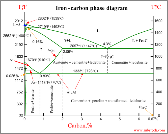
Carbon content 667 corresponds to the fixed composition of the iron carbide fe 3 c.

Iron carbon phase diagram. The percentage of carbon present and the temperature define the phase of the iron carbon alloy and therefore its physical characteristics and mechanical properties. Phase diagrams metastable iron carbon fe c phase diagram. Carbon is added to iron as an interstitial inclusion to improve the strength of iron.
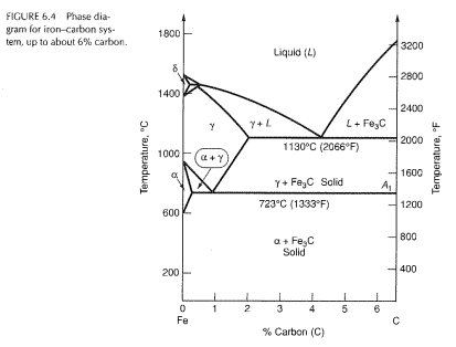
Dmitri kopeliovich iron carbon phase diagram describes the iron carbon system of alloys containing up to 667 of carbon discloses the phases compositions and their transformations occurring with the alloys during their cooling or heating. If carbon is added to iron it produces iron carbidefe 3 c phase which is hard and brittle in nature also called as cementite. The fe c phase diagram is a fairly complex one but we will only consider the steel part of the diagram up to around 7 carbon.
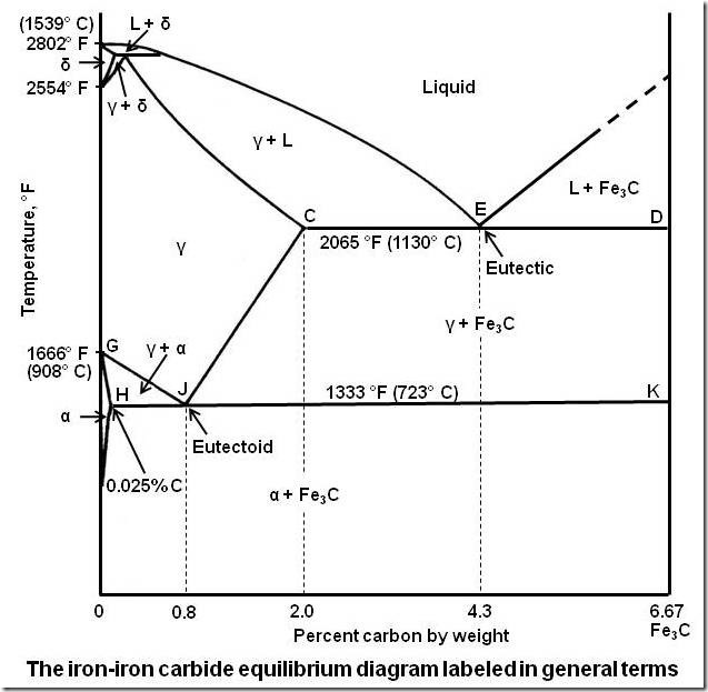
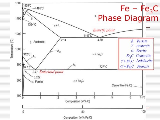
The ironiron carbide fefe 3 c phase diagram. The ironiron carbide fefe3c phase diagram in their simplest form steels are alloys of iron fe and carbon c. Iron steel or cast iron.
There is more to the iron carbon phase diagram than related in the backbone. The maximum solubility of carbonc in ironfe is 667 called as critical concentration. Iron carbon phase diagram with detailed explanation.
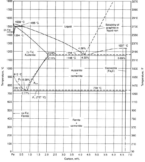
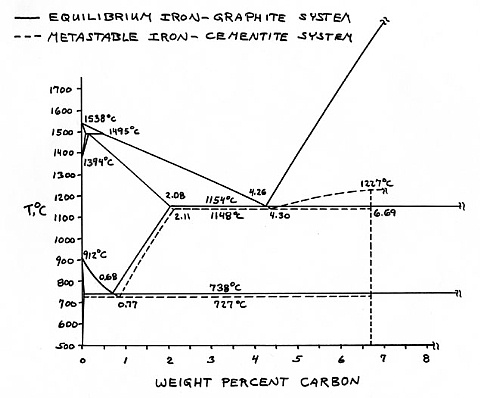
A study of the microstructure of all steels usually starts with the metastable iron carbon fe c binary phase diagram figure 1. This figure shows the iron carbon equilibrium diagram. The stable condition usually takes a very long time to develop specially in the low temperature and low carbon range hence the metastable diagram is of more interest.
The iron carbon diagram also called the iron carbon phase or equilibrium diagram is a graphic representation of the respective microstructure states depending on temperature y axis and carbon content x axis. In particular there is some nomenclature that i avoided in the main text but that is important for understanding other writings about iron and steel. It provides an invaluable foundation on which to build knowledge of both carbon steels and alloy steels as well as a number of various heat treatments they are usually subjected to hardening annealing.
On this diagram the carbon percentage is shown on the x axis and temperature on the y axis. Iron carbon phase diagram. Funda of mechanical engineering.
The different phases or mixture of phases occur in different areas enclosed by these. The diagram shown in fig 1 actually shows two diagrams i the stable iron graphite diagram dashed lines and the metastable fe fe3c diagram. In this diagram the lines indicate the boundaries where the alloy changes its phase.
The actual iron carbon diagram is far larger than the part shown here.

 Iron Carbon Phase Diagram Substech

 Iron Carbon Phase Diagram With Transformation Stress
 How To Remember Iron Carbon Phase Diagram Mechanical
 Iron Carbon Diagram The Influence Of Carbon
 Allotropes Of Iron Wikipedia
 Iron Carbon Phase Diagram Cementite Iron Png Clipart Free
 Iron Carbon Steel Phase Diagram W Pro Eutectoid Step
 Introduction Microstructures Cast Irons High Alloy
 Iron Carbon Phase Diagram

 Iron Carbide Phase Diagram List Of Wiring Diagrams
 Iron Iron Carbon Phase Diagrams Summary Notes Pdf Phase
 The Iron Carbon Phase Diagram
 Iron Carbon Phase Diagram Jane Schmoetzer Flickr
Metallurgy Matters Thermal Cycles The Haz And The
What Is The Difference Between An Iron Carbon And A Phase

 Iron Carbon Phase Diagram Iron Graphite Phase Diagram
 Iron Carbon Phase Diagram
Belum ada Komentar untuk "Iron Carbon Phase Diagram"
Posting Komentar