Dimming Ballast Wiring Diagram
This irs2530d used to be applied in linear dimming ballast 3 way dimming ballast and multi level switch dimming ballast. Variety of 0 10v dimming ballast wiring diagram.
 Dimming Ballast Wiring Diagramn Catalogue Of Schemas
View all legacy products systems.

Dimming ballast wiring diagram. A wiring diagram is a type of schematic which makes use of abstract photographic symbols to reveal all the affiliations of components in a system. Dimming ballasts are available for fluorescent tubes and cfls that use an external ballast. Dimming fluorescent lights are usually found in commercial and institutional environments and not common in the household.
These ballasts are usually rapid start or programmed start and have a good dimming range. Series ballasts can only be wired in series according to the diagram on the ballast. Below is the pin assignment function and datasheet of the irs2530d.
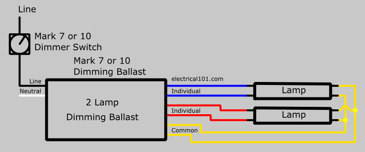
To find a diagram for a specific product or system please use the drop down menus below. Dimming ballast functions and protects the circuit against line and load fault conditions. The mark 10 powerlineballasts programmed start design optimizes lamp and dimming performance by monitoring system performance and making continuous adjustments.
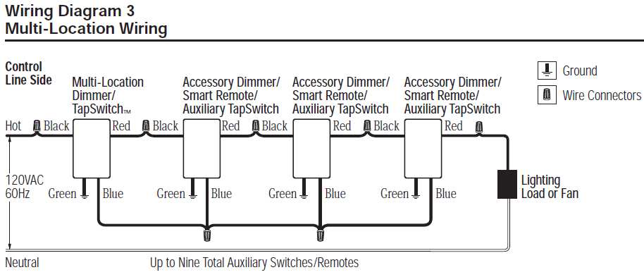
Search the lutron archive of wiring diagrams. Quick easy troubleshooting. A wiring diagram is a streamlined standard photographic representation of an electric circuit.
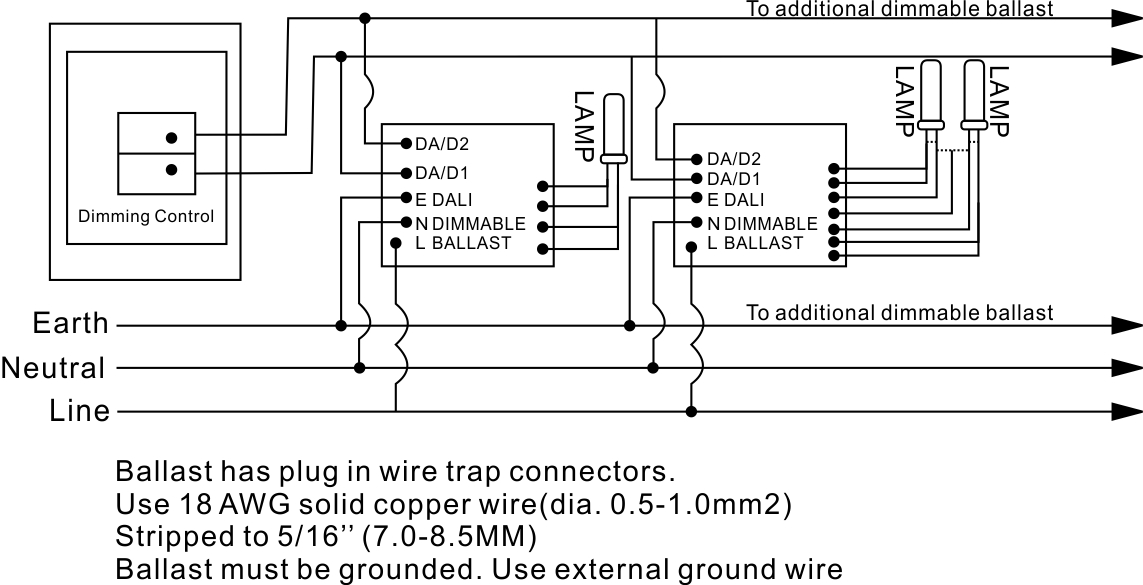
For longest lamp life and best filament contact use only approved or recommended sockets. 0 10v dimming wiring diagram 0 10v dimmer switch leviton ip710 lfz or equal for other types of dimming control systems consult controls manufacturer for wiring instructions switched hot black switched hot red typical low voltage dimming wires purple gray typical electrical panel hot black typical 120v or 277v 60 hz neutral white. Plus the mark 10 powerlinedoes not have to ramp up to full light output and then dim.
Dimming cfls and leds. 6 fluorescent dimming systems technical guide sockets lamp sockets when installing lutron ballasts socket type and wiring are importantgood pin to socket contact and correct wiring are requiredto produce flicker free dimming and ensure long lamp life. How to install a dimmer.
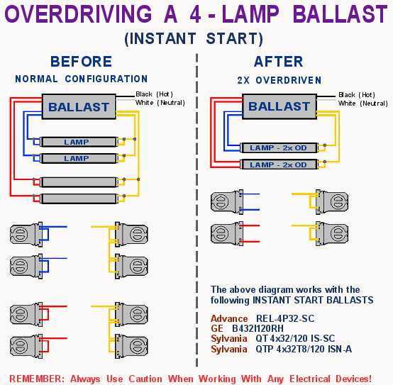
Changing the wiring on a fluorescent light fixture from series to parallel involves changing the ballast from a series to a compatible parallel ballast. It shows the elements of the circuit as simplified shapes and also the power and also signal connections in between the devices. Parallel ballasts can only be wired in parallel according to the diagram on the ballast.
0 10v dimming ballast wiring diagram just whats wiring diagram. The ballast will start lamps at the minimum dimming level increasing comfort levels for area.


 Wiring Diagram For Leviton Dimmer Switch New Lutron Dimming

 Lutron Skylark Dimmer Wiring Diagram Easy Lutron Dv 603p
 0 10v Dimming Wiring Diagram Another Blog About Wiring Diagram

 Lutron Dimmer Switch Wiring Diagram Download Wiring
3 L Dimming Ballast Wiring Diagram Wiring Diagram


 Lutron Dimming Ballast Wiring Diagram With Dimmer Switch In

 0 10v Dimming Ballast Wiring Diagram Collection Wiring
 T6 Ballast Wiring Diagram Wiring Diagrams Folder

 Led Downlight Wiring Diagram Uk 12v Australia Advance Driver


 Lutron Dimmer Switch Wiring Diagram Starfm Me


 Dimming Ballast Wiring Diagramn Wiring Diagram
Belum ada Komentar untuk "Dimming Ballast Wiring Diagram"
Posting Komentar