Digital Panel Meter Circuit Diagram
The manual and the circuit diagrams dont seem to turn anything up for me. The circuit for reducing the voltage the circuit consists of rx ry calculated as follows.
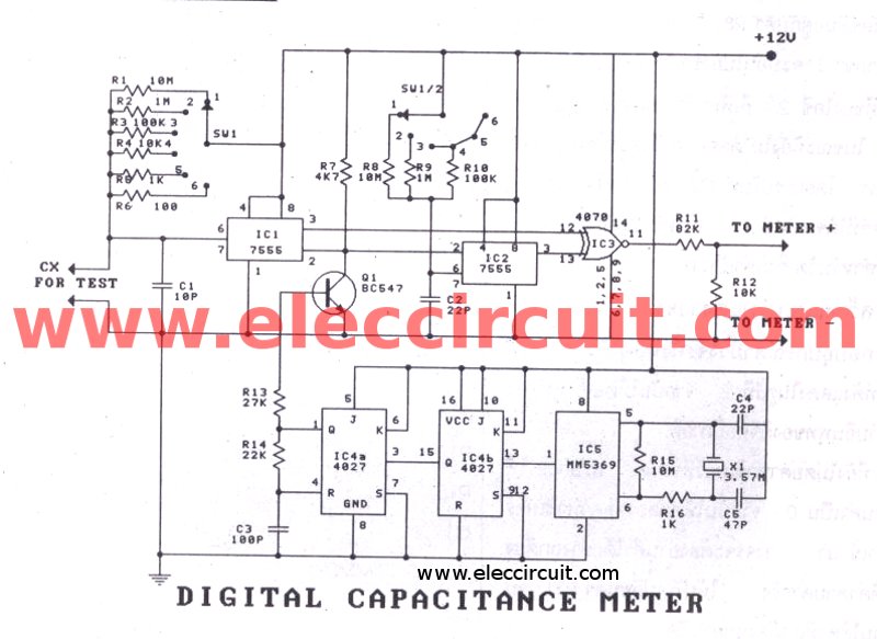 Digital Capacitor Meter Circuit Diagram Wiring Diagrams Folder
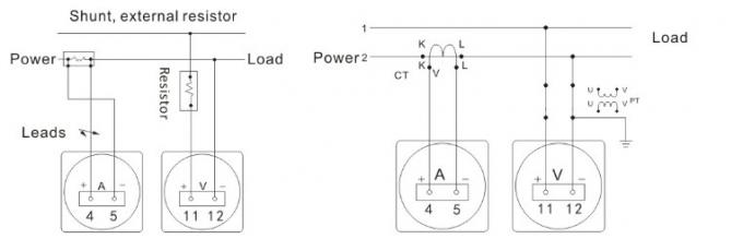
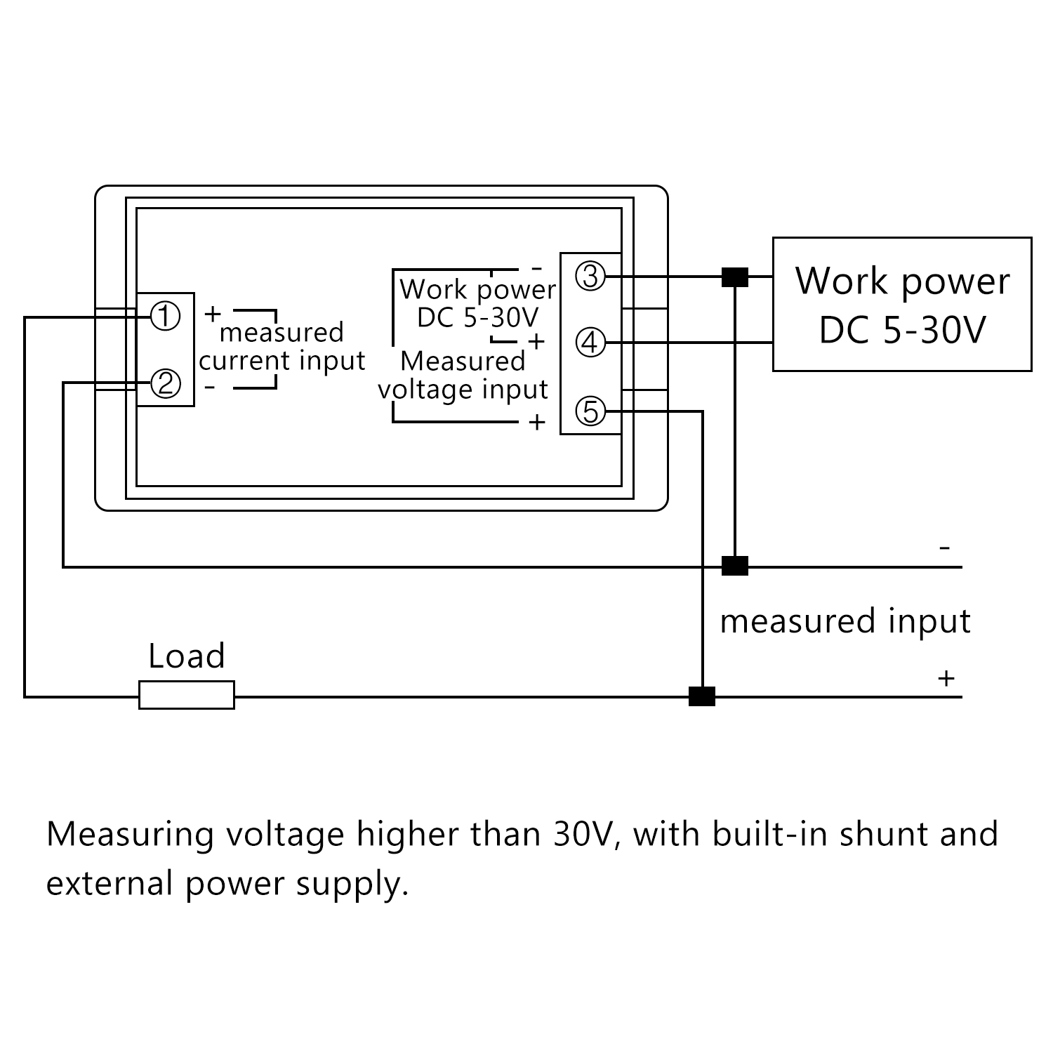
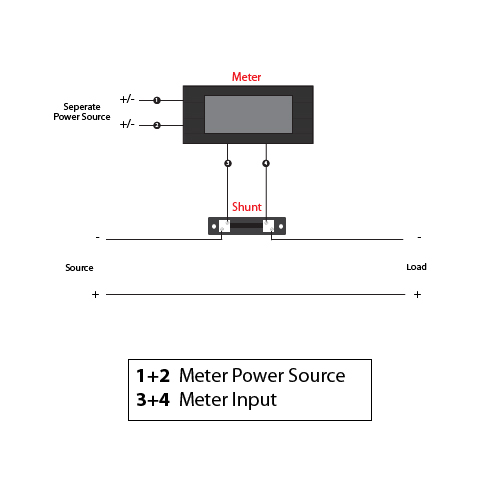
How to wire digital dual display volt and ammeter.

Digital panel meter circuit diagram. The meter is rated at 5 amps and has a 5vdc terminal which supplies the mp and lights the display and it also has a terminal block marked in of which i am not sure is wired in series or whether a shunt should be across these terminals and i doubt that it would be wired across the supply. Digital panel meter performs digital processing on or conversion and display of voltages currents other analog signals and pulse signals. If yes cooling fan is the load part and you cant just put solar panel as the load.
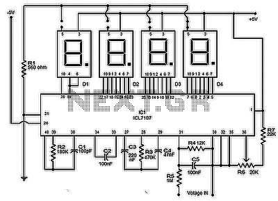
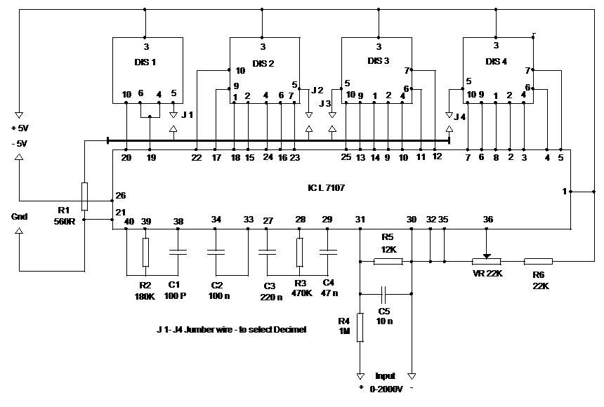
If you want more the voltage range. Needless to say the ic l7107 can be also rigged into a simple yet accurate panel digital voltmeter circuit which is what we are presently interested in. This meter runs only one way.
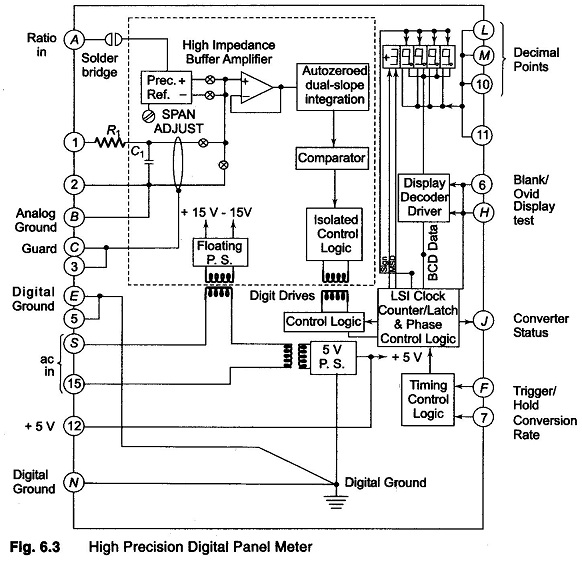
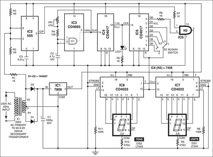
The circuit is low component one and the reading is reliable and accurate. This circuit is used in digital panel meters to give alpha numerical display. In figure 5 is the digital voltmeter circuit designed for general applications.
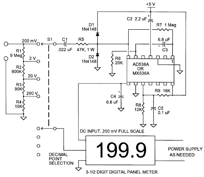
Shop for high accuracy lcd panel meters designed to display input signals in a wide variety of electronics applications voltmeter current meter ph meter etcthese meters have high resolution displays that are easy to read and we offer jumbo and backlit models for even greater visibility in any environment. I have a digital panel meter that i want to wire into a 30vdc power supply that can produce 25 amps. Referring to the circuit diagram below the unit is a full fledged digital voltmeter circuit which can be used for measuring direct voltages right from zero to 199 volts.
I always try my best to make simple and understandable diagram. Thanks in advance for any help. How to wire a panel analog ampere meter with ct coil.
Similar circuit distributor manual circuit diagram chip diagram. Figure 5 the simple dc digital meter circuit is completely. Incoming supply mean enter electric wire where we get electric power.
As in above ammeter wiring diagram i shown dam with ct in incoming supply and out supply to load. Hers is a digital ampere meter circuit diagram with ct. Which it requires the maximum range equal to 200mv.
A digital to analogue converter is in use in the circuit. They just use the negative because it makes it easier to design a circuit that works. Image of a digital panel voltmeter with a single ic l 7107 you can make a 4 digit voltmeter that can show 0 2000 voltsthrough seven segment display.
The cx102a digital panel meter from circuit specialists is ideal for this application as it is designed to use in a system that has the measured signal isolated from the power supply voltage. The application is for a 0 120 volt ac meter powered by an external 9 volt battery. It does however say that use as an ammeter is possible in the manual.
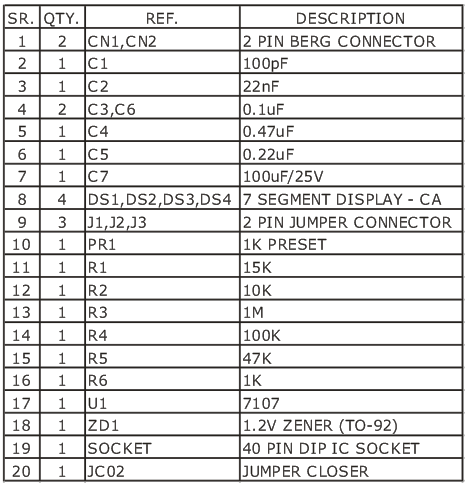
Which they can do. This project is based on popular icl 7107 ic which is analog to digital converter and has been designed to drive 7 segment led display.

 Power Meter Circuit Diagram List Of Wiring Diagrams
 Digital Panel Meters And Modules

 Digital Multimeters Digital Panel Meters Bench Type
 Ac Panel Ammeter Wire Diagram Wiring Diagram
 Ac Meter Wiring Diagram Wiring Diagram
 Measuring Power With A Digital Panel Meter Dpm Simply
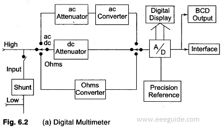
 Digital Multimeter

 Digital Multimeters Digital Panel Meters Bench Type

 Digital Panel Ammeter Wiring Diagram
 Voltage Meter Circuit Wiring Diagrams Show
 Digital Panel Meter Voltmeter Electronics Lab
 Frequency Meter Detailed Circuit Diagram Available
 Meters Multipliers And Shunts
 Picaxe Panel Meter
Belum ada Komentar untuk "Digital Panel Meter Circuit Diagram"
Posting Komentar