Motor Control Circuit Diagram Pdf
Although the heater elements are connected in series with the motor lines as fuses would be. You return to automation this time with the motor symbol in the cross hairs so all that remains doing is to place the symbol.
 Basic Wiring For Motor Control Technical Data Guide Eep
These devices are connected in series with the motor conductors and heat up slightly under normal current conditions.

Motor control circuit diagram pdf. Line diagrams also called schematic or elementary diagrams show the circuits which form the basic operation of the controller. Motor control page 12 tutorial. Line diagrams show circuits of the operation of the controller.
A very common form of latch circuit is the simple start stop relay circuit used for motor controls whereby a pair of momentary contact pushbutton switches control the operation of an electric motor. Press to get the next available number. For example the following can be considered motor controls.
Rev for three phase motor connection power and control diagrams. A particular application must satisfy the needs of the user and comply with applicable codes laws and standards before using any of the typical circuits shown in this publication. When you place the symbol on the page the dialog pops up now containing data about type and article no.
Three phase slip ring rotor starter control power diagrams. Bold lines denote the power circuit and thin lines are used to show the control circuit. All motors must have a control device to start and stop the motor called a motor controller.
Two speeds two directions multispeed 3 phase motor power control diagrams. 2 speeds 1 direction 3 phase motor power and control diagrams. It is important to note.
Understanding of motor control wiring dia grams. If you keep the word switch in mind it helps keep the intimidat ing subject of motor control in its proper context. A motor control circuit for the most part is simply a switch or group of switches and a motor.
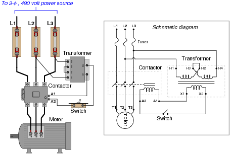
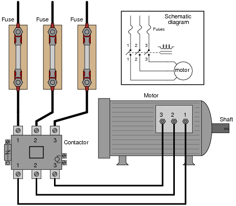
Black wires are conventionally used in power circuits and red wire in control circuits for ac magnetic equipment. Figure 1 is a typical wiring diagram for a three phase magnetic motor starter. The symbols used in this booklet were.
A special type of overcurrent protection device used commonly in motor control circuits is the overload heater. A motor controller is the actual device that energizes and de energizes the circuit to the motor so that it can start and stop. A wiring diagram is limited in its ability to completely convey the controllers sequence of operation.


 3 Phase Contactor Wiring Diagram Catalogue Of Schemas

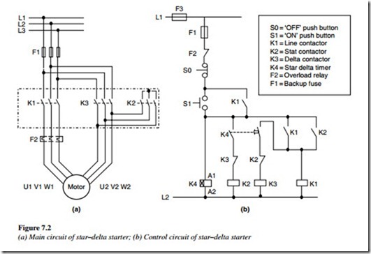
 Star Delta Motor Starter Circuit Diagrampdf Wiring Diagram
 3 Phase Motor Circuit Diagram Pdf Wiring Diagrams Folder
 Electrical Control Panel Wiring Diagram Wiring Diagrams
 Single Phase Motor Wiring Pdf Schematics Online
 Industrial Motor Control Diagrams Schematic Wiring Diagram
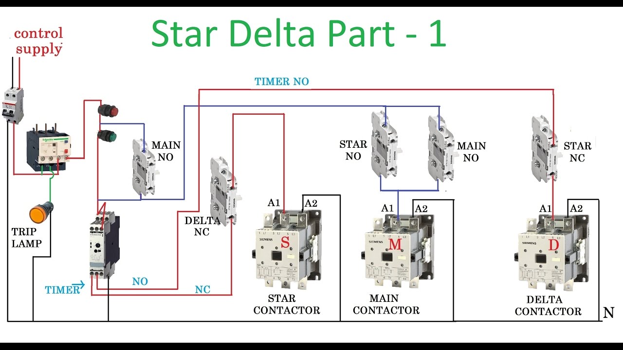 Star Delta Motor Starter Circuit Diagrampdf Wiring Diagram

 Motor Starter Circuit Diagram Pdf Car Wiring Diagram And
 3 Phase Motor Starter Circuit Diagram Swift Electrical Schemes


 Dc Motor Circuit Diagram Pdf Machine Learning
 Motor Starter Circuit Diagram Pdf Car Wiring Diagram And

Ac Motor Diagram Pdf Wiring Diagram Document Guide
Belum ada Komentar untuk "Motor Control Circuit Diagram Pdf"
Posting Komentar